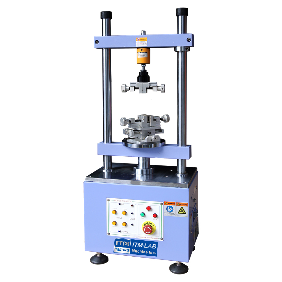
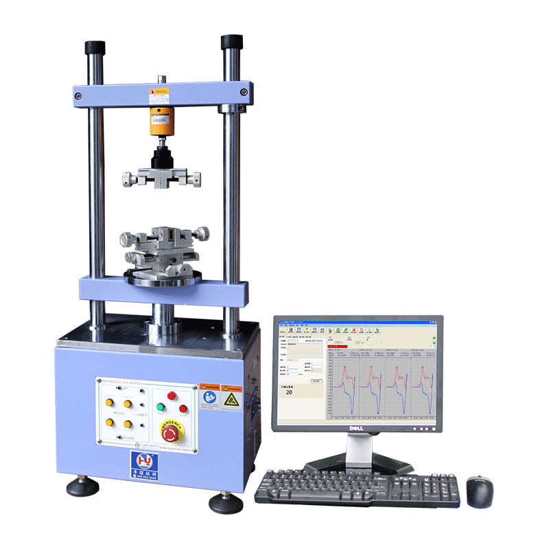
The Servo Control Automatic Tester RS-6600A is designed for various connectors for insertion force and pull out force test, equipped with automatic centering device with a variety of connector special fixtures, can get completely accurate insertion and pulling force results
Model: RS-6600A Purpose: The RS-6600A Auto Insert & Extract Tester is a high-precision testing device designed for various connectors. It accurately measures insertion and withdrawal forces and is suitable for tests such as pulling, pressure, and life tests. The device is equipped with an automatic centering system and specialized clamps, ensuring precise and reliable test results. It uses a Windows-based software interface, which simplifies operation and allows for automatic storage of test data (such as loading vs. displacement curves, loading attenuation life curves, and test results). All test conditions can be stored, making the machine easy to operate.
Typical Applications
Whole Row Plug Tests for Connectors
Single-Hole Plug Tests for Connectors
Connector Insertion and Withdrawal Life Tests
Connector Pin and Plastic Retention Force Tests
Connector Normal Force Tests
Connector Shrapnel Compression Tests
Connector Dynamic Impedance Tests
Various Tension and Pressure Tests
Features
Fully Automatic Testing Mode Simply input and store the test conditions for each test batch, and the machine will automatically conduct compression, tensile, and other tests. This high level of automation reduces operator workload and enhances testing efficiency.
Wide Applicability With the use of different clamps, the RS-6600A can test various connectors and other products. It is suitable for R&D, IQC finished product testing, as well as service life and dynamic impedance tests. The device automatically stores all test data and curves upon completion.
High Precision The machine uses a high-precision load cell. The load resolution is 0.01gf, and the displacement resolution is 0.001mm, ensuring highly accurate and reliable test results.
Flexible Unit Conversion The load units can be freely converted between N, gf, kgf, and Lb; displacement units can be switched between mm and cm to meet different user preferences.
Multilingual Support The RS-6600A is equipped with English, Simplified Chinese, and Traditional Chinese interfaces, making it easy to use for global customers.
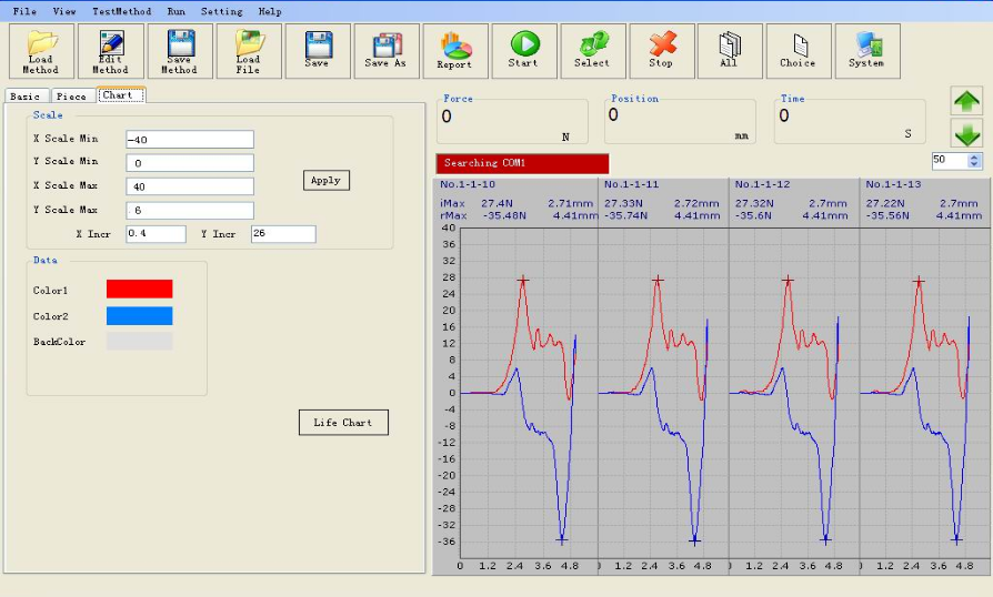
Large Memory Capacity All test data, including curves and raw data, are automatically stored on the computer's hard disk, with no limit on the number of records. All data can be accessed and retrieved at any time.
User-Friendly Design All test parameters such as loading, displacement, cycles, speed, and waiting time are easily set via the computer interface. The system is intuitive and simple to use.
Automated Report Generation Test results are automatically formatted into reports, including data and curve reports. The report titles can be modified (both in English and Chinese) as needed, and no additional data entry is required. Reports can be printed at any time.
Automatic Judgment and Test Result Analysis The system allows users to input the upper and lower limits for compression and tensile loads. It will automatically judge the test results (Passed or Failed) and provide detailed analysis, ensuring the accuracy and reliability of the test results.
Scroll-Type Graph Display The device automatically generates tensile and compression curves, with insertion represented by positive values and withdrawal by negative values, allowing users to easily interpret the test data.
Product Advantages
Precise and Reliable Measurements: Utilizing a high-precision load cell and servo motor drive system, the RS-6600A ensures accurate and consistent insertion force test results.
Powerful Data Storage and Analysis Capabilities: All test data is stored permanently, enabling easy retrieval and analysis at any time. The system also automatically analyzes test results, streamlining data processing.
Flexible Operation and Wide Application: Ideal for connector R&D, quality control, and life cycle testing, the RS-6600A is a versatile solution for manufacturers and testing facilities.
Excellent After-Sales Service and Technical Support: As a source manufacturer, we provide comprehensive technical support and after-sales service to ensure long-term, reliable operation of the equipment.
Applicable Industries
Electronics Manufacturing
Telecommunications Equipment Manufacturers
Connector Manufacturers
Testing Equipment Distributors
Research Labs and R&D Institutions
Conclusion
The RS-6600A Auto Insert & Extract Tester is the ideal choice for accurate and efficient connector force testing. With its high precision, automation, and powerful data management features, it will greatly enhance your testing capabilities and product development processes. Choose the RS-6600A today to boost your productivity and testing efficiency!
Designed for all kinds of capacitive touch screen module CTP, cell phone machine, tablet PC, e-book, electronic dictionary and other products touch screen to do click scratch test. It is suitable for capacitive screen precision test, jitter test, linearity test, sensitivity test, long time scratch test and long time click test.
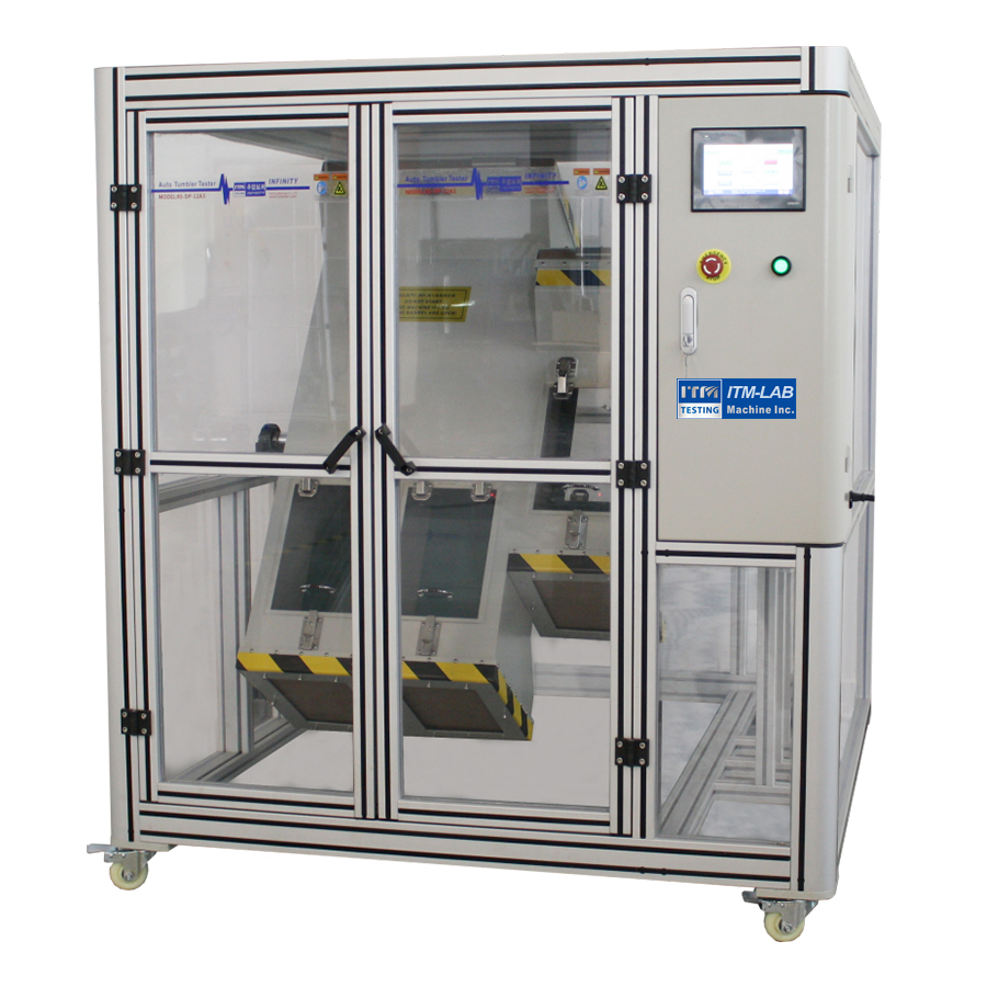
The RS-DP-12A Rolling Angle Drop Tester performs continuous rotation (rolling drop) tests for portable electronic products to verify impact resistance and structural reliability during daily use and transportation.
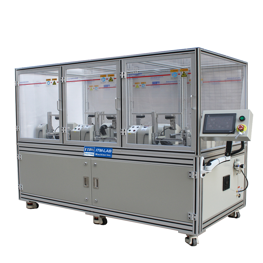
ITM-LAB RS-6303T Series foldable screen phone durability tester is designed for foldable devices, available in 4-station (RS-6303T-4) and 6-station (RS-6303T-6) models. With high precision, flexible adjustment and stable performance, it’s ideal for R&D and mass production QC, trusted by Samsung, OPPO ets.
Designed for various capacitive and infrared touch screen modules ( mobile phones, tablets, e-books, electronic dictionaries, etc.) and is capable of conducting click and scratch tests.For precision testing, jitter testing, linearity testing, sensitivity testing, long-duration scratch testing, and long-duration click testing of capacitive screens.
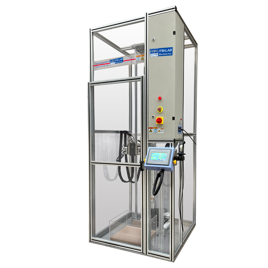
The Automatic Drop Test Machine RS-DP-03A2 is designed to evaluate the impact on product performance when a customer accidentally drops the product during actual use. It is suitable for directional drop tests on portable consumer electronic products such as mobile phones, tablets, chargers, e-books, electronic dictionaries, batteries, touch screens, headphones, etc.
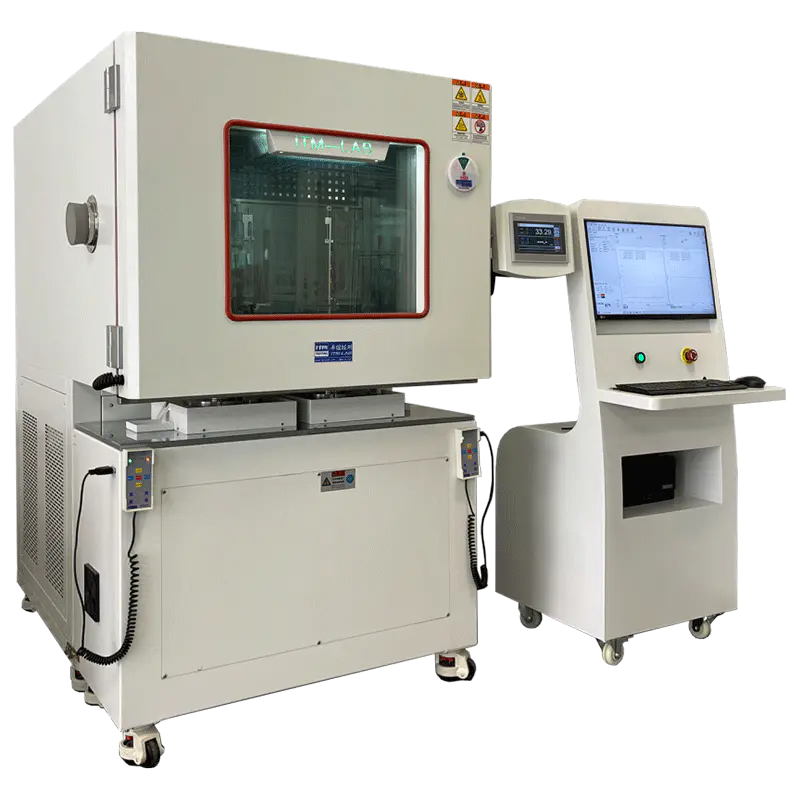
The High and low temperature automatic torque testing Machine RS-6300G-HLT is designed for torsion test and life test of folding screen cell phone machine, PI flexible screen, ammonium chain mechanism, UTG module, FPC, etc. under high & low temperature environment.
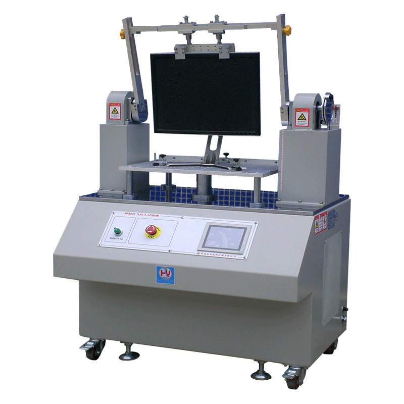
The Spindle Torque Endurance Testing Machine rs-6700(servo type) is designed for LCD MONITOR liquid crystal display, V liquid crystal TV, all-in-one computer, etc. After many times of forward tilt and backward swing test, whether the rotor shaft still has the holding force or the rotor shaft resistance becomes large and damages the plastic body.
The RS-8106C is a specialized torsion life tester designed to evaluate the durability and lifespan of the swivel mechanism on over-ear headphones. By simulating continuous rotation under configurable angles and speeds, it ensures that headphone joints can withstand repeated usage without failure—ideal for R&D, quality control, and benchmarking.
Contact information
No. 32 Qiaoxin East Road, QiaotouTown, Dongguan City,Guangdong Province,China