
What is ASTM D412 and ISO 37?
Full Standard Titles:
-
ASTM D412: "Standard Test Methods for Vulcanized Rubber and Thermoplastic Elastomers—Tension"
-
ISO 37: "Rubber, vulcanized or thermoplastic — Determination of tensile stress-strain properties"
Scope:
Both standards govern the determination of tensile stress-strain properties of high-elongation materials at a regulated room temperature (23 plus/минус 2°C / 73.4 plus/минус 3.6°F). Unlike metallic materials, elastomers exhibit hyperelastic, highly non-linear behaviors without a distinct yield point. Therefore, these methods target stress values at specified elongations (tensile modulus), ultimate tensile strength, and elongation at break.
Applicable Materials:
-
Vulcanized rubbers (natural and synthetic rubbers like NR, SBR, NBR, EPDM)
-
Thermoplastic elastomers (TPE)
-
Thermoplastic polyurethanes (TPU)
-
Silicone rubbers (VMQ) and fluorocarbon elastomers (FKM)
-
Latex products, elastic films, and flexible cellular materials (with limitations)
Key Differences: ASTM D412 vs ISO 37
-
ASTM D412: Administered by ASTM International. It separates methodologies into Method A (flat dumbbell/dogbone specimens) and Method B (cut ring specimens). It accommodates both inch-pound and metric systems.
-
ISO 37: Administered by ISO. It is exclusively metric-centric and defines 4 primary types of dumbbell specimens and 2 types of ring specimens, which feature distinct geometric proportions that differ from the American configurations.
Related Standards:
-
GOST 270: Rubber. Method of tensile testing (the direct Russian domestic equivalent to ISO 37)
-
ISO 23529: General procedures for preparing and conditioning rubber test pieces
-
ASTM D573: Standard test method for rubber deterioration in an air oven (tensile properties are profiled post-environmental aging via D412)
Standard Sources: ASTM International (
Test Equipment Requirements
Universal Testing Machine (UTM) Specifications
Per ASTM D412 Section 6 - Apparatus:
Load Measurement:
-
Accuracy: Within plus/minus 1% of the verified readout in compliance with ASTM E4 or ISO 7500-1 (Class 1).
-
Load Cell Capacity: The absolute ultimate breaking force of the elastomeric matrix must not exceed 80% of the load cell's full capacity. Due to relatively low forces required for rubber testing, high-resolution, low-capacity cells (250 N to 5 kN) are highly recommended.
-
Calibration: Mandatory annual verification with traceable metrological certification.
Crosshead Speed & Displacement Control:
-
The system must maintain stable, constant crosshead travel under load at:
-
500 plus/minus 50 mm/min (for standard ASTM D412 Method A and ISO 37 Type 1, 2, and 3 specimens).
-
200 plus/minus 20 mm/min (mandated for small Type 4 geometries under ISO 37).
-
-
Speed Precision: Within plus/minus 2% of the set parameter.
-
Vertical Frame Clearance: Net crosshead travel must reach at least 1000 mm (ideally 1200 mm to 1400 mm). This is critical because highly elastic polymers with a 25 mm initial gage length stretching to 800% require more than 250 mm of stroke just for material deformation, excluding grip dimensions.
Axial Alignment:
-
The longitudinal axis of the dogbone specimen must align precisely with the center line of the load string. Misalignment generates non-axial shear stresses, leading to premature tearing at the grip boundary.
Gripping and Clamping Systems
Requirements per ASTM D412 Section 6.2:
Pneumatic Side-Action Grips (Highly Recommended):
-
Utilizes constant, regulated pneumatic pressure throughout the entire test cycle.
-
Automatic Specimen Thinning Compensation: As the rubber specimen undergoes high tensile elongation, its cross-sectional thickness collapses exponentially. The pneumatic actuator continually drives the jaw faces inward, eliminating specimen slippage.
Self-Tightening Eccentric / Roller Grips:
-
Employs a cam-lock mechanism where the clamping intensity increases proportionally with the applied tensile force.
-
Acceptable for routine QA screening, though they require meticulous manual centering during mounting.
-
Jaw Face Texture: Must be smooth, rubber-coated, or feature a flat wave-profile. Serrated or knurled steel faces (typical for ASTM E8 metal testing) are strictly prohibited as they slice into the soft matrix, inducing jaw breaks.
Common Operational Issue:
Standard manual screw grips cause specimen slippage, which shows up on the stress-strain curve as flat plateaus or load drops, rendering modulus calculations impossible.
Extensometer Requirements (Strain Measurement)
ASTM D412 Section 6.4 — Strain Acquisition:
Class Designation per ASTM E83:
-
Class D or superior (demanding displacement verification within plus/minus 10% over large travel increments).
Non-Contact Video Extensometers (Preferred Methodology):
-
Fully compliant with ASTM D412 Appendix X2 criteria.
-
An optical camera tracks retroreflective or high-contrast markers applied to the narrow section of the specimen.
-
Advantage: Zero physical contact. This eliminates physical knife-edge stress concentration on the soft rubber and prevents hardware damage when the polymer forcefully snaps at break.
Mechanical Long-Travel Extensometers:
-
Utilizes dual counterbalanced, ultra-light contact arms.
-
Dynamic Range: Must provide steady tracking up to 1000% relative elongation.
-
Safety Mechanism: Arms must automatically decouple or retract fractions of a second prior to structural fracture to shield internal components.
Specimen Preparation
Standard Specimen Geometries
Dumbbell (Dogbone) Configurations per ASTM D412 (Method A):
Standard Type C Specimen (Global Industry Standard):
-
Width of Narrow Section (W): 6.0 plus/минус 0.05 mm
-
Length of Narrow Section (L): 33 plus/минус 2 mm
-
Gage Length / Base Measurement (G): 25.0 plus/минус 0.5 mm
-
Transition Fillet Radius (R): 14.0 plus/минус 1.0 mm
-
Overall Length (A): 115 mm minimum
-
Nominal Thickness (T): 1.5 mm to 3.0 mm range (Standard target: 2.0 plus/минус 0.2 mm)
Micro Geometries (Types D, E, F):
-
Applied when raw compounding material is limited or when reclaiming samples from final commercial parts (seals, O-rings, tubes).
ISO 37 / GOST 270 Dumbbells
Standard Type 2 Specimen (Close Equivalent, but structurally distinct):
-
Width of Narrow Section (W): 6.0 plus/минус 0.2 mm
-
Length of Narrow Section (L): 25 plus/минус 1 mm
-
Gage Length / Base Measurement (G): 20.0 plus/минус 0.5 mm
-
Transition Fillet Radius (R): 14.0 plus/минус 1.0 mm
-
Overall Length (A): 75 mm minimum
Geometric Proportions:
Due to the variance in initial gage lengths (25 mm for ASTM vs 20 mm for ISO), raw strain data cannot be directly substituted between standards.
Die Cutting and Preparation Protocol
ASTM D412 Section 7 — Fabrication:
Die Stamping Standards (Штанцевые ножи):
-
Specimens must be stamped from cured polymer sheets using a mechanical or hydraulic clicker press.
-
Cutting dies must undergo micro-inspection every 500 cuts. Dull edges produce microscopic nicks or "flash" on the dogbone’s side flank, initiating premature failure.
-
Blade Lubrication: Pure water or a mild soap-water solution is permitted. Petroleum-based lubricants are strictly prohibited—they swell the rubber and alter cross-link density.
Dimensional Tolerances:
-
Parallelism along the narrow neck: Within 0.05 mm variance.
-
Edge Finish: Perfectly uniform with zero tool-marks or stepping from the die.
Gage Marking:
-
Gage marks (G) must be applied using a non-contact template and elastic inks free of aggressive solvents. Screwing, scratching, or physically indenting the rubber surface is strictly prohibited.
Geometry Measurement:
-
Thickness must be captured using a benchtop dial micrometer equipped with a flat circular anvil (4 mm to 8 mm diameter) exerting a regulated dead-weight pressure of 22 plus/минус 5 kPa (to prevent compressing the soft matrix). Take measurements at three distinct spots within the narrow section; use the minimum cross-sectional area for initial stress computing (A0).
Testing Procedure
Pre-Test Preparation
ASTM D412 Section 8 — Operational Steps:
-
Environmental Conditioning:
-
Ambient Testing Temp: Maintained at 23 plus/минус 2 °C (per ISO 23529 protocol).
-
Relative Humidity: 50 plus/минус 10% standard.
-
Thermal Equilibrium: Samples must rest in the controlled environment for a minimum of 3 hours before undergoing mechanical strain.
-
Data Logging:
-
Measure and record width and thickness to the nearest 0.01 mm.
-
The UTM software automatically populates the initial cross-sectional area (A0).
-
Frame Initialization:
-
Install the pneumatic side-action grips.
-
Set the initial jaw-to-jaw separation: 75 plus/минус 5 mm (for Type C specimens).
-
Hardcode crosshead speed to 500 mm/min.
-
Set data acquisition sampling frequency to at least 50 Hz to accurately capture the material fracture point.
Step-by-Step Test Execution
Step 1: Specimen Mounting
-
Secure the top tab of the rubber dogbone in the upper grip jaws vertically.
-
Execute a Load Tare command to zero out the mass of the specimen.
-
Secure the lower tab in the bottom grip jaws. Ensure the rubber hangs flat without sagging or generating compressive forces (the baseline load should read 0 N plus/минус 0.1 N).
Step 2: Pull Initiation
-
Enable data logging for the load-extension diagram.
-
Engage the crosshead to travel upward at a steady rate of 500 mm/min.
Step 3: Continuous Strain Tracking
-
The extensometer (optical or mechanical) measures the real-time distance between the gage lines (L) continuously.
-
The software correlates the instantaneous force (P) with real-time strain. At 100% and 300% strain checkpoints, the software automatically tags the force indicators (P100 and P300).
Step 4: Ultimate Fracture
-
The crosshead maintains 500 mm/min until physical structural failure occurs.
-
Upon fracture, the load drops instantly. The software logs the peak force (Pmax) and final elongation length (Lf) reached immediately prior to tearing.
Step 5: Post-Test Cleanup (Optional)
-
Release the spent sample tabs.
-
If measuring Tension Set, align the broken fragments on a flat surface, allow a 10-minute relaxation window for the high-elastic deformation to recover, and record the permanent displacement change between the gage lines.
Data Calculation and Reporting
Tensile Stress at a Given Elongation (Modulus)
Elastomers do not possess a distinct yield point like metals. Engineers instead calculate stress values at predefined elongation checkpoints (typically 100% Modulus or 300% Modulus):
Calculation Protocol:
-
The software catches the exact timestamp where gage strain hits 100% (gage distance doubled) or 300% (gage distance quadrupled).
-
The force values (P100 or P300) are extracted.
-
The stress metric (MPa) is calculated via:
Stress = P_E / A_0
Where:
-
Stress = Tensile stress at given elongation (MPa)
-
P_E = Force captured at specified strain (N)
-
A_0 = Original cross-sectional area (W x T, mm²)
Ultimate Tensile Strength (Tensile Strength)
ASTM D412 Section 11.2:
Calculated by dividing the absolute maximum force recorded before failure by the original cross-sectional area:
TS = P_max / A_0
Where:
-
TS = Ultimate Tensile Strength (MPa)
-
P_max = Maximum breaking force (N)
Note: Even though the true cross-section of the elastomer shrinks dramatically before break, the standard mandates calculation relative to the original area A0.
Ultimate Elongation (Elongation at Break)
ASTM D412 Section 11.3:
Expressed as a percentage change over the original gage length:
E_b (%) = [(L_f - L_0) / L_0] x 100
Where:
-
L_0 = Initial gage distance (e.g., 25 mm for Type C)
-
L_f = Final distance separating gage marks at the precise instant of break (mm)
Typical Elastomeric Baseline Properties:
| Material | Elongation at Break (%) | Ultimate Tensile Strength (MPa) |
| Natural Rubber (cured) | 400 - 700 | 18 - 28 |
| Nitrile Rubber (NBR) | 250 - 500 | 12 - 22 |
| Thermoplastic Polyurethane (TPU) | 500 - 1000 | 25 - 55 |
| Fluoroelastomer (FKM / Viton) | 150 - 350 | 8 - 18 |
| Silicone Rubber (VMQ) | 200 - 600 | 6 - 12 |
Test Report Requirements
Mandatory metrics required in a compliant report per ASTM D412 Section 12:
-
Material Fingerprinting:
-
Compound grade, batch numbers, curing dates/regimes.
-
Stamping orientation (longitudinal or transverse to calendar flow).
-
Geometry Records:
-
Die classification (e.g., ASTM Type C or ISO Type 2).
-
Mean thickness, width, and cross-sectional area metrics for each sample.
-
Total sample count per series (Minimum 5 samples required for statistical significance).
-
Environmental and System Blueprint:
-
UTM model name and extensometer type.
-
Exact tracking rate (500 mm/min).
-
Ambient lab temperature and humidity values.
-
Tabular Results:
-
Tensile stress at 100% and 300% elongation (MPa).
-
Ultimate tensile strength (MPa).
-
Elongation at break (%).
-
Statistical analysis: Mean, median, and standard deviation calculations for the batch.
Common Testing Issues and Technical Solutions
Issue 1: Dumbbell Slippage Inside the Grip Jaws
Symptoms:
-
Force vs. displacement curves exhibit sudden flattening, jagged steps, or erratic load loss.
-
Elongation values are artificially inflated.
Root Cause:
-
Relying on manual screw grips. As the rubber stretches and narrows, jaw clamping force is lost.
Corrective Action:
-
Swap out manual hardware for pneumatic side-action grips linked to a steady air regulator.
-
For dense TPEs (Hardness >45 Shore D), install jaw faces with a smooth, flat wave profile.
Issue 2: Dumbbell Failures Occurring at the Grip Boundary (Jaw Breaks)
Symptoms:
-
Greater than 20% of a sample batch fails right along the jaw exit line.
-
Artificially low values for both tensile strength and elongation.
Root Cause:
-
Excessively high air pressure in the pneumatic grips, causing the sharp jaw edge to cut the rubber.
-
Poor axial alignment creating transverse twisting.
Corrective Action:
-
Lower the pneumatic regulator pressure to the minimum threshold required to hold the sample without sliding.
-
Transition to grip faces with radiused or chamfered edges to ease stress concentration.
Issue 3: Wild Data Scatter Across a Single Material Batch
Symptoms:
-
Standard deviation for ultimate tensile properties exceeds 15%.
Root Cause:
-
Micro-tears along the dumbbell edge due to a chipped or dull cutting die (штанцевый нож).
Corrective Action:
-
Send the cutting die out for precision sharpening or replace it.
-
Inspect the stamping anvil base; utilize a dense plastic backer plate (such as high-density nylon or Delrin) to ensure a clean cut without tearing the lower face.
Standard Comparison: ASTM D412 vs ISO 37
Core Methodological Variances:
-
Reference Specimen (ASTM D412 Method A): Type C is the default geometry. Uses a 25 mm gage length.
-
Reference Specimen (ISO 37): Type 2 is the primary European geometry. Uses a 20 mm gage length. Its shorter neck shifts the initial elastic slope upward slightly on stress graphs.
-
Displacing Speeds (ASTM D412): Strictly locked at 500 plus/минус 50 mm/min for Method A.
-
Displacing Speeds (ISO 37): Adaptive. For ultra-small Type 4 dogbones, speed is dialed back to 200 mm/min to prevent signal damping in the load train.
Practical Implication:
Data generated using ASTM Type C dies cannot be directly substituted for ISO Type 2 data in engineering spec sheets. Direct testing under the governing standard is mandatory for formal ISO 17025 lab accreditation.
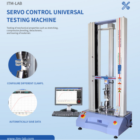
ITM-LAB Testing Systems for Elastomers
ITM-LAB builds high-stability universal testing machines specifically optimized for high-elongation polymers, backed by 27 years of deep application expertise.
Hardware Capabilities:
-
Vertical Frame Extension: Custom-extended single and dual-column frames provide up to 1300 mm to 1500 mm of clean crosshead stroke, handling elastomers up to 1200% elongation easily.
-
High Resolution Sensing: Force measuring precision hits Class 0.5 (ISO 7500-1), exceeding standard ASTM E4 boundaries.
-
Servo Architecture: Precision AC servo drive assemblies maintain seamless speed control from 0.01 to 1500 mm/min with zero feedback lag.
The Turnkey ASTM D412 / ISO 37 Package Includes:
-
Pneumatic parallel side-action grips with a foot-pedal control box (keeps the technician's hands free to position soft rubber dogbones accurately).
-
High-speed Video Extensometer or Long-Travel contact extensometer engineered to follow high elongation velocities.
-
ITM-LAB Software Suite preloaded with automated standard testing libraries for one-click 100%, 300% modulus, and ultimate break reporting.
For equipment specifications, application notes, and standard quotes, contact our application engineering branch at our technical portal:WA +86 18102960079
Conclusion
Achieving reproducible tensile metrics for vulcanized rubbers and TPEs under ASTM D412 and ISO 37 relies on three pillars: maintaining razor-sharp die cutting, enforcing crosshead speed stability (500 mm/min), and applying continuous clamping pressure to offset specimen thinning.
Adhering to these strict practices ensures your laboratory reports stand up to rigorous external audits and comply fully with ISO 17025 lab accreditation requirements.
📧 Contact Template
Contact us to get a high cost-effective Tensile tester quotation:
ITM-LAB Global Inquiry Platform
