
Peel adhesion testing is a core quality control and R&D metric used to evaluate the interfacial bond integrity between an adhesive matrix and a specified substrate. Unlike standard tensile specifications that evaluate bulk material limits, peel testing measures the localized resistance of a bond line to progressive mechanical separation.
This guide provides an in-depth technical analysis of the two most critical industrial peeling standards: ASTM D903 (universal adhesives) and ASTM D3330 (pressure-sensitive tapes). It outlines testing apparatus parameters, substrate preparation requirements, data-reduction workflows, and targeted hardware solutions based on current standard updates and ITM-LAB’s 27 years of application experience.
Understanding the Standards: ASTM D903 vs. ASTM D3330
While both standards utilize a universal testing machine (UTM) to execute controlled peeling, they target entirely different classes of adhesive systems and configurations.
ASTM D903: Standard Test Method for Peel or Stripping Strength of Adhesive Bonds
-
Scope: Designed for universal, structural, or semi-structural adhesives bonding flexible or semi-rigid backings (e.g., rubber, films, fabrics, plastics) to rigid substrates.
-
Peel Angle: Strictly a 180-degree configuration. The flexible backing is folded completely back on itself and pulled parallel to the bond line.
-
Crosshead Velocity: Mandated at 152 mm/min (6 in./min).
-
Key Challenge: The flexible backing must possess sufficient pliancy to yield a zero-radius bend at the peel front without tearing or adding substantial bending force to the load readout.
ASTM D3330: Standard Test Method for Peel Adhesion of Pressure-Sensitive Tape
-
Scope: The definitive standard for Pressure-Sensitive Adhesives (PSAs), including masking tapes, packaging tapes, double-sided acrylic foam tapes (VHB), and electronic component protection films.
-
Method Varieties: Contains six sub-methods (Methods A through F). The most widely deployed industrial variations include:
-
Method A (180-degree peel): Tape is applied to a standard steel panel and peeled back at 180 degrees.
-
Method F (90-degree peel): Tape is peeled away perpendicular to the test panel, crucial for thicker or semi-rigid tape backings.
-
-
Crosshead Velocity: Fixed at 300 mm/min (12 in./min).
-
Key Challenge: Highly sensitive to application pressure, substrate surface chemistry, and microscopic variations in the peeling angle.
Critical Equipment & Fixture Requirements
To secure high repeatability and eliminate laboratory-induced data variance, the testing machine and tooling footprint must conform to precise mechanical constraints.
Universal Testing Machine (UTM) & Load Cell Specifications
Since peel forces for thin films and tapes are typically low, high-stiffness single-column or light dual-column benchtop frames are optimal. Utilizing a high-capacity load cell (e.g., 50 kN) introduces catastrophic signal-to-noise errors when testing low-force adhesives. For precise peel evaluation, low-capacity load cells (10 N, 50 N, or 100 N maximum) are required. The system must maintain a resolution of 0.5% of the applied force or finer, ensuring accurate capture of subtle micro-peeling characteristics.
Furthermore, the electronic controller must sustain a high data acquisition frequency (minimum 50 Hz to 100 Hz). Low sampling rates smooth out critical stick-slip peaks, corrupting the average force values.
Special Grip & Fixture Configurations
-
180-Degree Peel Setup (ASTM D903 / ASTM D3330 Method A): Requires a standard pneumatic side-action or mechanical vice grip to clamp the rigid substrate in the lower section, while an upper lightweight grip pulls the folded backing.
-
90-Degree Sliding Peel Fixture (ASTM D3330 Method F): When executing a 90-degree pull, the peeling point advances along the plate over time. If a fixed plate is used, the angle changes dynamically from 90 degrees to an oblique angle. To prevent this, a specialized mechanical sliding bed or motorized 90-degree tracking fixture is used. The carriage moves horizontally in perfect lockstep with the vertical crosshead displacement, maintaining a strict 90-degree vector at the peel front throughout the entire cycle.
Substrate Preparation and Laydown Protocols
Peel forces are deeply influenced by surface energy, clean boundary layers, and application pressure. Improper specimen preparation accounts for over 80% of testing errors in industrial labs.
The Standard Stainless Steel Test Panel
Per ASTM D3330 specifications, annealed AISI 302 or 304 stainless steel panels must be ground to a bright, uniform polish with a controlled surface roughness rating of 50 ± 25 nm arithmetic average deviation. Panels must be washed with reagent-grade isopropyl alcohol or diacetone alcohol using lint-free surgical gauze. Any residual oils, fingerprint films, or airborne contaminants will dramatically suppress the apparent peel adhesion.
The 2.0 kg Mechanized Standard Roller
Pressure-sensitive adhesives require a controlled compressive load to fully wet out across the substrate micro-topology. Standard hand pressure or uncalibrated plastic wipers are strictly prohibited. A standard rubber-covered steel roller weighing 2.0 ± 0.1 kg (4.5 ± 0.1 lb) must be used.
The roller must pass over the tape specimen twice (one pass forward, one pass backward) at a constant velocity of approximately 600 mm/min (24 in./min). No additional downward manual force may be applied to the roller axis. This ensures identical wet-out characteristics across all comparative material samples.
Data Analysis and Calculations
Defining Peel Strength
Peel strength is defined as the average force required to progressively separate a flexible member from a substrate, normalized by the specimen's linear width. The calculation is formatted as follows:
Peel Strength = F_avg / W
Where:
-
Peel Strength is expressed in Newtons per millimeter (N/mm), Newtons per 25mm (N/25mm), or ounces per inch (oz/in).
-
F_avg is the calculated average peeling force (N or oz) recorded across a stable testing window.
-
W is the measured linear width of the adhesive strip or tape (mm or in).
The Data-Reduction Window
A typical peel test profile exhibits an initial force spike as the bond line first undergoes cleavage (the initiation zone). To ensure data integrity, the software must exclude this startup artifact and any terminal deceleration zone. The average peel force (F_avg) must be computed exclusively over the middle 50% to 80% of the total peeled length.
Mandatory Classification of Failure Modes
A complete peel test report must go beyond numerical load data; the engineer must visually audit and declare the exact mode of structural failure:
-
Adhesive Failure (Interfacial Tearing): The adhesive matrix separates cleanly from the substrate panel, leaving zero visible residue. This reflects the true interfacial bond strength.
-
Cohesive Failure: The adhesive layer splits down its center, leaving a thick film of residue on both the backing and the substrate panel. This indicates that the internal cohesion of the polymer is weaker than its surface adhesion.
-
Substrate / Backing Failure: The tape backing or flexible strip tears, deforms plastively, or undergoes layer delamination before the adhesive line separates. The report must state that the absolute adhesive strength exceeds the tensile limits of the carrier material.
Common Troubleshooting Matrix
| Observed Symptom | Potential Root Cause | Engineering Solution |
| Severe "Stick-Slip" Jagged Force Curves | Natural viscoelastic oscillation of highly cohesive PSAs at high strain rates. | Do not average the raw peaks manually. Utilize software algorithms that calculate the true mathematical median or mean load across the stable 80% core window. |
| Artificially High Force Readings at 180° | The flexible backing material is too thick or rigid, causing the UTM to record the energy required to bend the substrate alongside the actual peel force. | Switch to a 90-degree sliding peel fixture layout to eliminate the 180-degree folding stress entirely. |
| Premature Tearing of the Carrier Strip | Edge defects or micro-nicks introduced along the tape flank by a dull cutting blade during sample preparation. | Upgrade to precision industrial razor cutters or dual-blade specimen cutters to guarantee perfectly smooth, defect-free specimen edges. |
| Inconsistent Peel Force across Samples | Variations in dwell time between rolling the sample and executing the pull. | Standardize the open dwell window. Per ASTM D3330, execute the pull either immediately (under 1 minute) or after a controlled aging phase (e.g., 20 minutes or 24 hours). |
Turnkey Solutions from ITM-LAB for Peel & Adhesion Testing
Precise adhesion mapping demands meticulous mechanical control and high system responsiveness. ITM-LAB provides dedicated, turnkey testing packages configured to meet the rigorous demands of ASTM D903, ASTM D3330, and equivalent international guidelines.
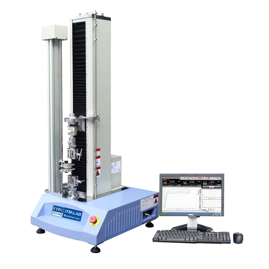
1. ITM-LAB RS-8010A Single Column Tensile Test Machine
For standard benchtop tape and adhesive testing, the
-
Low-Capacity Precision: The RS-8010A supports highly sensitive load cells including 50N, 100N, 200N, and 500N configurations, perfectly isolating low-force peeling data from background noise.
-
Velocity Stability: With a test speed range from 0.01 to 500 mm/min and a displacement resolution of 0.001 mm, it ensures perfectly stable crosshead movement at the exact velocity profiles mandated by ASTM standards.

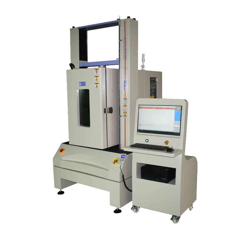
2. Advanced Environmental Profiling: RS-8000GDW
For advanced industrial applications—such as automotive interior trim backing or aerospace sealants that require testing under extreme temperatures—ITM-LAB offers the
3. Specialized Tooling & Software Integration
To convert your system frame into a dedicated adhesion analyzer, ITM-LAB provides specialized hardware and software components:
-
Dedicated Peeling Fixture: Designed for stable substrate retention, our specialized
Peeling Fixture -
Multilingual Intelligent Software: Powered by an advanced Windows-based testing suite, our software features automatic calculation of average/median peel forces across customized percentage zones. For global laboratory integration, the application supports instant runtime translation between English, Russian, Chinese, Japanese, French, and German.

To request a formal engineering evaluation, discuss custom fixture geometries, or obtain a comprehensive system quotation, visit our international support network at the
📧 Inquiry & Conversion Gateway
For customized fixture dimensions, detailed technical specifications, or a tailored product quotation, submit your operational criteria directly to our global engineering team via the:
ITM-LAB Global Inquiry Platform .
