
.webp)
Evaluating the mechanical properties of metallic materials requires more than just standard tensile profiles. To completely map out a metal’s behavioral boundaries in real-world structural or manufacturing environments, engineers must deploy a triad of mechanical stresses: tension, compression, and bending.
While ASTM E8/E8M(For information on ASTM E8/E8M test methods, please click) dominates North American tensile applications, international global supply chains frequently mandate adherence to European and International standards (ISO 6892-1). Furthermore, capturing compressive yielding properties (ASTM E9) and evaluating ductility or crack resistance under structural forming (ASTM E290) are vital steps for comprehensive quality control and R&D.
This technical guide provides a practical blueprint, calculations, troubleshooting procedures, and hardware configurations for executing tests under these three critical standards.
1. ISO 6892-1: Tensile Testing of Metallic Materials at Room Temperature
Scope and Context
ISO 6892-1 is the international baseline standard for tensile testing of metals at ambient temperatures (10°C to 35°C). While it shares a similar core objective with ASTM E8, ISO 6892-1 is significantly stricter regarding strain rate control tolerances and proportional specimen geometries.
Specimen Preparation & Geometry Rules
A foundational difference in ISO 6892-1 is its strict reliance on proportional test pieces, where the original gauge length (L0) is directly tied to the original cross-sectional area (A0).
-
Proportional Formula: L0 = k * √(A0)
-
Standard International Coefficient (k): 5.65
For a standard round specimen with diameter d0, this cross-relates mathematically to: L0 = 5.65 * √(π * d0² / 4) ≈ 5 * d0
Machining Quality Standards:
-
Surface Finish: Gauge section must be machined to 1.6 μm Ra (63 microinches) or better.
-
Thermal Protection: Avoid cold working or induction heating during specimen extraction. Copious coolant must be applied during grinding or turning.
-
Parallelism: The parallel reduced section must be uniform within 0.08 mm over its entire length.
Testing Rates: Method A (Strain-Rate Controlled) vs. Method B (Stress-Rate Controlled)
ISO 6892-1 places massive emphasis on minimizing human or machine-induced data scattering by defining two test speed protocols:
-
Method A (Preferred): Based on strain-rate closed-loop control utilizing extensometer feedback. This minimizes stress-rate spikes when transitioning from elastic to plastic zones.
-
Elastic Range Target: 0.00025 s⁻¹ with a strict tolerance of ±20%.
-
-
Method B: Based on traditional stress-rate control.
-
Elastic Range Target for Steel: 6 MPa/s to 60 MPa/s.
-
Step-by-Step Engineering Calculation Example
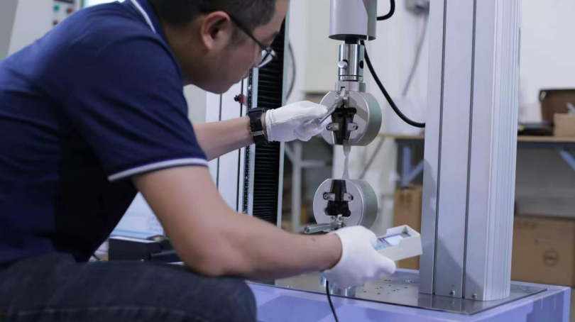
Let us evaluate a structural steel proportional round specimen on an ITM-LAB Universal Testing Machine (UTM).
Given Parameters:
-
Original Diameter (d0) = 10.0 mm
-
Original Gauge Length (L0) = 50.0 mm
-
Force at Yield Point (Fp at 0.2% offset) = 27,800 N
-
Maximum Peak Force (Fm) = 43,200 N
-
Final Gauge Length after fracture (Lu) = 62.5 mm
Step A: Calculate Original Cross-Sectional Area (A0)
-
A0 = π * d0² / 4
-
A0 = 3.14159 * 10² / 4 = 78.54 mm²
Step B: Determine 0.2% Proof Strength (Rp0.2 / Yield Strength)
-
Rp0.2 = Fp / A0
-
Rp0.2 = 27,800 N / 78.54 mm² = 353.96 MPa
Step C: Determine Tensile Strength (Rm)
-
Rm = Fm / A0
-
Rm = 43,200 N / 78.54 mm² = 550.04 MPa
Step D: Calculate Percentage Elongation After Fracture (A)
-
A (%) = [(Lu - L0) / L0] * 100%
-
A (%) = [(62.5 - 50.0) / 50.0] * 100% = 25.0%
2. ASTM E9: Compression Testing of Metallic Materials at Room Temperature
Why Compression Testing Matters
Many engineering materials—such as cast irons, bearing alloys, and structural composites—are utilized primarily under compressive loads. Testing these materials under tension does not provide an accurate representation of their true structural performance. ASTM E9 dictates the procedures for determining compressive yield strength, compressive modulus, and ultimate compressive strength.
The Challenge of Barreling and Buckling
Unlike tensile tests where stress aligns naturally, compression testing forces suffer from two major geometric anomalies:
-
Barreling: Frictional forces between the testing machine's loading platens and the specimen ends restrict lateral expansion, forcing the cylinder into a barrel-like shape.
-
Buckling: If the specimen is too tall relative to its diameter, it will fail due to column buckling rather than pure compressive deformation.
To counteract this, ASTM E9 establishes strict slenderness ratios (Length-to-Diameter ratio, L/D):
-
Short Specimens (L/D = 0.9 ± 0.1): Used for determining the ultimate compressive strength of high-strength or brittle materials.
-
Medium Specimens (L/D = 3.0 ± 0.1): The standard general-purpose specimen layout used for determining compressive yield strength and stress-strain curves.
-
Long Specimens (L/D > 8.0): Used specifically for checking column stability and buckling tendencies.
   [Standard Medium Compression Specimen Alignment]

                 Force (↓)
         ┌───────────────────────┐  ─── Upper Hardened Platen
         │ ///////////////////// │
         └──────────┬────────────┘
                    │
              ┌─────┴─────┐
              │           │ ◄─── Specimen (L/D = 3.0)
              │           │
              └─────┬─────┘
                    │
         ┌──────────┴────────────┐
         │ ///////////////////// │
         └───────────────────────┘  ─── Lower Sub-press Base
                 Force (↑)
Essential Apparatus Requirements
To execute an authentic ASTM E9 test, a specialized Compression Sub-press or spherical-seated bearing block is mandatory. The loading surfaces must be hardened to at least 60 HRC and lapped flat to within 0.005 mm to maintain perfect parallelism during the stroke.
Engineering Calculation Example
Given Parameters (Medium Specimen):
-
Nominal Specimen Diameter (d0) = 13.0 mm
-
Nominal Length (L0) = 39.0 mm (L/D = 3.0)
-
Yield Load at 0.2% compressive strain offset (Fcy) = 51,500 N
Step A: Calculate Compressive Cross-Sectional Area (A0)
-
A0 = π * d0² / 4
-
A0 = 3.14159 * 13.0² / 4 = 132.73 mm²
Step B: Determine Compressive Yield Strength (σcy)
-
σcy = Fcy / A0
-
σcy = 51,500 N / 132.73 mm² = 388.00 MPa
3. ASTM E290: Standard Test Methods for Bend Testing of Material for Ductility
Scope and Engineering Significance
ASTM E290 assesses a metal’s capacity to undergo plastic deformation during bending operations without developing surface fractures or cracks. It is heavily utilized by quality control teams inspecting structural steel plates, weldments, and sheet metal forming stocks.
Unlike a flexural test designed to measure structural modulus, the primary pass/fail criterion of an ASTM E290 test is a visual surface evaluation for microscopic fissures after the specimen has reached a target bend angle.
Core Testing Configurations
ASTM E290 outlines four primary bending arrangements, with the Guided Bend Test and Semi-Guided Bend Test being the most prevalent in industrial quality frameworks:
-
Guided Bend (Mandrel/Plunger Type): The specimen is forced down into a die by a mandrel of a specific radius (r). The outside surface of the bend undergoes intense tensile strain.
-
Semi-Guided Bend (V-Die Type): The specimen is supported at two points and pressed in the center until it conforms to the target angle (typically 90° or 180°).
      [ASTM E290 Semi-Guided Bend Setup]

               [Plunger / Mandrel]
                     │  Radius (r)
                     ▼
                 ┌───────┐
                 │       │
    ~~~~~~~~~~~~~└─┬───┬─┘~~~~~~~~~~~~~ ◄─── Specimen
                   │   │
              ▲    │   │    ▲
              │    └───┘    │
         ┌────┴────┐     ┌──┴──────┐
         │ Support │     │ Support │    ◄─── Roller Supports (Distance Ls = 2r + 3t)
         └─────────┘     └─────────┘
Determining the Bend Parameters
The severity of the test is governed by the ratio of the mandrel radius (r) to the specimen thickness (t), designated as the r/t ratio. A smaller radius indicates a harsher test.
Test Geometry Rule:
The distance between the supports (Ls) for a standard semi-guided setup is calculated as:
-
Ls = 2r + 3t ± t
(Where r = Radius of the bending mandrel, t = Thickness of the test specimen)
Post-Test Visual Inspection Protocol
Upon completing the bend to the specified angle (180° for maximum severity), the specimen is removed. The outer convex surface of the bent portion is inspected under a minimum of 5× magnification.
-
Pass Criteria: Completely smooth surface, or micro-cracks smaller than the specified limit in the material standard (typically < 0.8 mm).
-
Fail Criteria: Visible surface tearing, structural splitting, or open cracks intersecting the edges.
4. Technical Comparison Matrix
| Testing Aspect | ISO 6892-1 (Tensile) | ASTM E9 (Compression) | ASTM E290 (Bend/Ductility) |
| Primary Stress Mode | Uniaxial Tension (Pulling) | Uniaxial Compression (Crushing) | Combined Tensile (Outer) & Compressive (Inner) |
| Key Mechanical Outputs | Yield (Rp0.2), Ultimate (Rm), Elongation (A%) | Compressive Yield (σcy), Modulus, Deformation Limits | Pass/Fail Crack Resistance, Max Bend Angle |
| Critical Setup Factor | Closed-loop strain rate control (Method A) | Platens parallelism, lubrication, L/D ratio | Mandrel radius-to-thickness ratio (r/t), Springback allowance |
| Common Specimen Forms | Proportional round bars, flat sheets | Precision machined solid cylinders | Flat rectangular bars, full-thickness plates |
5. Common Testing Issues & Solutions (Troubleshooting Guide)
Issue 1: Specimen Slippage in Tensile Grips (ISO 6892-1)
-
Symptoms: Non-linear stress-strain curve in the early elastic region; specimen physically slides out of wedge faces.
-
Causes: Worn tooth serrations on the grip faces or incorrect clamping pressure.
-
Solutions: Replace wedge inserts if serrations are worn smooth. For hydraulic grips, ensure pressure matches material hardness. Clean scale or oil off the specimen grip tabs using a mild solvent.
Issue 2: Premature Fracture in the Fillet Radius or Grip Area
-
Symptoms: The specimen breaks outside the marked gauge length (L0), invalidating the elongation data.
-
Causes: Severe stress concentrations due to poor machining transitions or axis misalignment of the UTM.
-
Solutions: Verify specimen fillet radius complies with the standard minimum. Run a frame alignment verification check per ASTM E1012 quarterly to eliminate bending strain.
Issue 3: Inconsistent Compressive Yielding / Barreling (ASTM E9)
-
Symptoms: High standard deviation across multiple compression tests; asymmetrical sample deformation.
-
Causes: High friction at the platen interfaces or non-parallel specimen end faces.
-
Solutions: Apply high-pressure lubricants (e.g., molybdenum disulfide) to the platen surfaces. Ensure specimen ends are ground flat and parallel within 0.01 mm.
Issue 4: Lateral Shifting During Bend Tests (ASTM E290)
-
Symptoms: The specimen slides off-center during plunger contact, causing asymmetrical bending angles.
-
Causes: Roller supports are out of alignment or not equidistant from the plunger axis.
-
Solutions: Use a dedicated centering jig to align the raw specimen across both lower rollers before initiating the crosshead stroke.
6. Mandatory Test Report Requirements
A valid mechanical test report under these international standards must include the following metadata fields to comply with ISO 17025 laboratory audits:
-
Material Traceability: Heat/Lot number, specification grades (e.g., S355JR, Al6061-T6), product form (plate, sheet, forged bar), and rolling orientation.
-
Geometric Properties: Verified initial dimensions (d0, L0, A0, t, r) measured to the nearest 0.02 mm.
-
Apparatus Specifications: Testing machine model, calibrated load cell serial number, and extensometer accuracy class (Class B-2 or better).
-
Calculated Test Data:
-
Tensile: Yield strength (Rp0.2), Tensile strength (Rm), Elongation (A%).
-
Compression: Compressive yield (σcy).
-
Bending: Final bend angle, mandrel r/t ratio, and pass/fail surface description.
-
ITM-LAB Turnkey Testing Systems for ISO, ASTM, and EN Standards
Executing complex cross-disciplinary testing procedures requires an adaptable, high-precision load frame combined with intelligent control software. ITM-LAB's High-Class Universal Testing Machines (50kN to 600kN) are purposely configured to swap seamlessly between tensile, compressive, and bending arrangements.
          [ITM-LAB Inter-changeable Actuator Fixtures]

     Tensile (Wedge Grips) ➔ Compression (Lapped Platens) ➔ Bend (ASTM E290 Rig)
        ┌──────────────┐          ┌──────────────┐          ┌──────────────┐
        │  [======]    │          │  ┌────────┐  │          │    ▼ Plunger │
        │  ▲ Specimen  │          │  │Specimen│  │          │  ~~~/~~~     │
        │  [======]    │          │  └────────┘  │          │  ▲   ▲ Rollers│
        └──────────────┘          └──────────────┘          └──────────────┘
Why Global Labs Choose ITM-LAB:
-
Exemplary Load Accuracy: Engineered to meet and exceed Class 0.5 under ISO 7500-1 and ASTM E4 calibration rules.
-
Dynamic Closed-Loop Control: Our advanced servo system natively tracks ISO 6892-1 Method A real-time strain-rate metrics, eliminating data jumps during material yielding phases.
-
Heavy-Duty Built-in Safety Features: Integrated overload thresholds, travel limits, and an instantaneous dual-circuit emergency shutdown system protect laboratory technicians.
-
Pre-Loaded Standard Software Library: Our specialized testing software platform features a native library of pre-coded evaluation algorithms for ISO 6892-1, ASTM E9, and ASTM E290, enabling single-click automation from calibration to custom PDF report rendering.
Ready to Upgrade Your Materials Testing Laboratory?
Don’t let suboptimal machine compliance compromise your material certifications. Our global application engineering team is ready to analyze your material matrix and configure the exact load frames, gripping configurations, and high-accuracy extensometer setups your operation demands.
[Contact ITM-LAB Engineering Experts Today] for a comprehensive, highly cost-effective technical consultation and machine quote tailored precisely to your operational budget.
Visit our official compliance hub at: https://www.itm-lab.com/contact.html
