
In the plastics and polymer industries, material characterization is everything. Whether you are compounding raw resins, injection molding automotive components, or manufacturing thin packaging films, ensuring the mechanical integrity of your material is critical to preventing field failures.
However, polymers exhibit complex viscoelastic behavior. Their mechanical properties change drastically based on ambient temperature, strain loading rates, molecular orientation, and specimen preparation. To maintain global alignment across resin suppliers, compounding plants, and contract manufacturers, testing laboratories must adhere strictly to international standards like ASTM and ISO.
This guide provides a comprehensive technical breakdown of the foundational mechanical testing standards for plastics, troubleshooting protocols for testing engineers, and the exact machinery configurations required to deliver reproducible, audit-proof data.
1. Tensile Properties of Rigid and Semi-Rigid Plastics (ASTM D638 and ISO 527-1/-2)
Apparatus Requirements (Section 6)
-
Load Measurement: Must conform to ASTM E4 or ISO 7500-1 accuracy requirements, delivering precision within +/-1% or +/-0.5% of the indicated load.
-
Strain Rate Control: Universal Testing Machines (UTMs) must maintain closed-loop constant crosshead speeds. Common speed settings are 5 mm/min, 50 mm/min, or 500 mm/min, depending on the material classification (rigid vs. non-rigid) and specimen type.
-
Extensometer: Class B-2 or better (per ASTM E83) is required for measuring tangent modulus and yield points.
Specimen Geometry and Conditioning (ASTM D618)
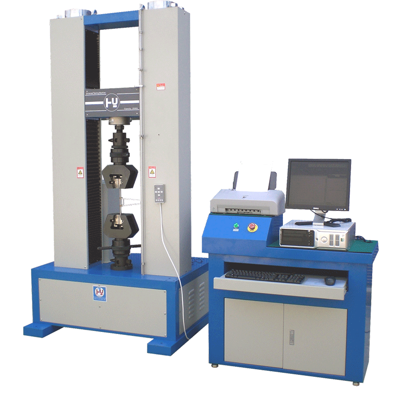
Unlike metals, polymers exhibit high hygroscopic and thermal sensitivity. Prior to mounting any specimen on a [ dual-column universal testing machine], laboratories must follow the conditioning guidelines in ASTM D618:
-
Standard Laboratory Atmosphere: Condition specimens at 23 +/- 2 degrees Celsius and 50 +/- 10% relative humidity for a minimum of 40 hours prior to testing.
-
Machining Pitfalls: When milling dumbbell specimens from sheets, sharp cutting tools and continuous cooling are mandatory. Micro-cracks or heat generation during milling will induce local crystallization, shifting the ductile-to-brittle transition point and corrupting elongation statistics.
Standard specimens are molded or machined into "dogbone" (dumbbell) geometries to isolate the stress distribution within the narrow gage section.
Specimen Geometry and Dimensions (ASTM D638 Type I)
| Dimension (ASTM D638 Type I) | Symbol | Size (mm) | Size (inch) |
| Width of Narrow Section | W | 13 +/- 0.5 | 0.50 +/- 0.02 |
| Gage Length | G | 50 +/- 0.2 | 2.00 +/- 0.01 |
| Distance Between Grips | D | 115 +/- 5 | 4.50 +/- 0.20 |
| Overall Length | L | 165 minimum | 6.50 minimum |
| Thickness | T | 3.2 +/- 0.4 | 0.13 +/- 0.02 |
Crucial Test Execution Checklist
-
Speed Consistency through Yield: Polymers are strain-rate sensitive. A sudden shift or lack of precision in crosshead speed alters the calculated yield strength and elongation at break.
-
Modulus Capture: Crosshead travel measurements incorporate machine frame deflection and grip compliance. For pure elastic modulus calculation, an axial clip-on or non-contact extensometer must be deployed directly onto the specimen's gage length.
2. Flexural Strength and 3-Point Bending (ASTM D790 and ISO 178)
Apparatus Requirements
-
Flexural Fixture: A three-point loading rig consisting of two support anvils and one central loading nose.
-
Nose and Support Geometry: The loading nose and supports must have cylindrical surfaces with radii of 5.0 +/- 0.1 mm unless specified otherwise.
-
Deflection Measurement: Deflection must be measured using a crosshead position indicator or a direct strain-gauge deflectometer meeting ASTM E83 Class B-2 requirements.
Specimen Preparation and Testing Setup
-
Geometry: Rectangular bars machined from sheet material or directly injection-molded. Standard bar size for ASTM D790 is 64 x 12.7 x 3.2 mm (2.5 x 0.5 x 0.125 inches).
-
Support Span Configuration: The support span-to-depth ratio must be set strictly to 16:1.
-
Formula: Span = 16 x T (where T = Specimen Thickness)
-
Failure to align the span to this specific ratio introduces unwanted shear stresses that invalidate the calculated flexural modulus.
3. Compressive Properties of Rigid Plastics (ASTM D695 and ISO 604)
Apparatus Requirements
-
Compression Tooling: Platen designs must feature high-rigidity structural steel. Platens must be parallel to within 0.02 mm across their entire surface area.
-
Slotted Support Fixture: For specimens thinner than 3.2 mm (0.125 inch), a specialized anti-buckling support jig is mandatory to keep the specimen vertically aligned during loading.
Technical Challenges: Buckling and Parallelism
The core challenge in compressive testing is ensuring purely axial loading. If the specimen ends are not perfectly perpendicular to the longitudinal axis, or if the platens exhibit a parallel offset, the sample will buckle or slip sideways. This off-axis shifting causes a premature bending failure rather than true structural crushing.
4. Tensile Testing for Thin Plastic Sheeting and Films (ASTM D882)
Apparatus Requirements
-
Applicability: Designed for flexible polymeric sheets, strips, and films with a thickness under 1.0 mm (0.04 inch).
-
Grip Geometry and Clamping Face: Conventional serrated metal grips cannot be used; they puncture thin films, causing immediate stress localization and premature failures at the jaw line. Smooth, rubber-coated, or flat, line-contact pneumatic grips are mandatory.
-
Load Cell Capacity: Low-force sensitivity is essential. Film rupture forces are incredibly low; therefore, high-resolution load cells mounted on a [ benchtop single-column tensile tester] must be utilized to maintain high data sampling resolution.
Specimen Design and Strain Measurement
-
Geometry: Uniform straight strips of constant width (10 mm to 50 mm), cut cleanly with no nicks or ragged edges using a precision specimen cutter.
-
Elongation Measurement: Because lightweight films cannot support the physical weight of a standard contact clip-on extensometer, ASTM D882 allows elongation tracking via crosshead displacement or non-contact video extensometry.
5. Technical Comparison: ASTM vs. ISO Polymeric Standards
Many contract manufacturers face compliance overlap when upgrading quality control labs. Testing a polymer under ASTM protocols may produce data that is entirely non-compliant with ISO standards due to structural and calculation variances.
Tensile and Flexural Comparison Matrix
| Testing Metric | ASTM Protocol | ISO Protocol |
| Tensile Specimen Geometry | ASTM D638: Type I Dumbbell (165mm Length) | ISO 527-2: Type 1A Multipurpose (170mm Length) |
| Tensile Modulus Zone | Segment between 0.05% and 0.25% strain (Alternative zone allowed) | Strict Chord Modulus calculated strictly between 0.05% and 0.25% strain |
| Initial Grip Distance | 115 +/- 5 mm for Type I | 115 mm for Type 1A / 125mm for Type 1B |
| Flexural Span-to-Depth | ASTM D790: Fixed at 16:1 standard span | ISO 178: Fixed at 16:1 (Requires stricter physical alignment) |
| Flexural Speed Logic | Calculated based on outer fiber strain rate (0.01 mm/mm/min) | Fixed testing speeds determined by specimen class (normally 2 mm/min) |
| Flexural Strain Sensor | Crosshead displacement acceptable for short support spans | Direct deflection separation sensor (Deflectometer) required for modulus |
6. Step-By-Step Test Execution Protocol for Plastics
To minimize human error and ensure cross-laboratory reproducibility, laboratory operators should execute the following five-step sequence:
-
Step 1: Dimensional Micrometer Verification: Measure the width and thickness of the narrow section of the dogbone at three distinct positions using a calibrated flat-anvil micrometer. Input the absolute minimum cross-sectional area into the software to ensure the engineering stress calculation reflects the weakest failure point.
-
Step 2: Symmetric Specimen Clamping: Mount the specimen into the upper grip first. Reset the force indicator on the control software to zero to eliminate the structural mass weight of the specimen. Lower the crosshead and engage the bottom grip. Ensure the specimen axis aligns perfectly with the center axis of the load frame to avoid inducing bending stress.
-
Step 3: Extensometer Engagement and Strain Control: Attach the Class B-2 clip-on extensometer onto the gage section. Start the test routine using a slow speed (typically 1 mm/min or 5 mm/min) to capture the initial linear-elastic slope.
-
Step 4: Extensometer Removal Threshold: Once the testing software accurately plots the linear slope and identifies the yield point (or passes 2% total strain), pause the crosshead travel or configure the automatic software threshold to carefully remove the contact extensometer. This safeguards the sensitive internal knife-edges from the violent energy release during ultimate material fracture.
-
Step 5: Post-Yield Testing to Rupture: Accelerate the crosshead speed (e.g., up to 50 mm/min or 500 mm/min) as specified by the standard class to pull the polymer through its plastic deformation zone until ultimate structural tearing or rupture occurs.
7. Data Calculation and Reporting Criteria
0.2% Offset Yield Strength (ASTM D638 / ISO 527)
To determine the yield point for polymers showing an indefinite proportional limit:
-
Plot the engineering stress (Formula: Stress = Load / Original Area) against the engineering strain (Formula: Strain = Change in Length / Original Gage Length).
-
Identify the linear portion of the elastic curve and determine its slope (Tensile Modulus).
-
Construct a line parallel to this slope, starting at 0.002 mm/mm (0.2%) on the strain axis.
-
The intersection point between the offset line and the stress-strain curve defines the yield strength.
Flexural Strength Formula (ASTM D790)
For a standard rectangular specimen tested on a 3-point bend setup:
-
Formula: Flexural Strength = (3 x P x L) / (2 x b x d^2)
Where:
-
P = Load at a given point on the deflection curve (N)
-
L = Support span (mm)
-
b = Width of beam tested (mm)
-
d = Depth or thickness of beam tested (mm)
8. Common Testing Issues and Laboratory Troubleshooting
-
Issue 1: Specimen Slippage or "Jaw Breaks" in Films (ASTM D882): The plastic film pulls free from the clamps during tension or tears precisely along the grip face edge. -> Solution: Transition to pneumatic grips to maintain constant, uniform pressure throughout the test. Ensure the jaw faces are covered with premium flat rubber inserts to eliminate localized shear stresses.
-
Issue 2: Inconsistent Modulus Values in Rigid Plastics (ASTM D638): High standard deviation across a single batch of identical polymers. -> Solution: Use a dedicated Class B-2 extensometer to isolate sample strain from system compliance. Ensure all dumbbell specimens are prepared via a precision specimen cutting press or injection mold to guarantee uniform gage thickness.
9. Comprehensive Polymer Testing Equipment Configurations
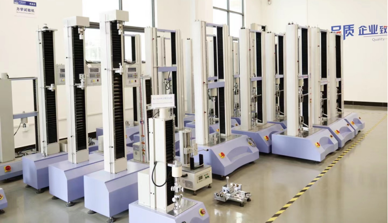
For laboratories looking to deploy testing infrastructures fully compliant with international polymeric standards, selecting the appropriate machine configuration is vital.
Equipment Architecture and Selection Guide
| Application Scope | Recommended Platform | Technical Specifications & Custom Role |
|
Rigid Materials Characterization (ASTM D638, D790, D695) |
[RS-8000 Dual-Column Platform] | High-rigidity dual-column chassis engineered for forces from 100N up to 50kN. Features a Level 0.5 equipment accuracy profile and 0.001mm displacement resolution to eliminate structural frame deflection errors during high-load crushing and bone pulling. |
|
Thin Film and Foil Precision (ASTM D882) |
[ RS-8010A Single-Column System] | Optimized for low-force film tearing and flexible materials where large frames lack signal resolution. Configured with highly sensitive interchangeable 50N to 5kN load cells and an explicit 1/500,000 load resolution. |
|
Thermal-Mechanical Evaluation (Automotive & Aerospace QC) |
[ RS-8000GDW Environmental System] | Integrates a closed-loop climate chamber allowing standard ASTM D638/D790 protocols to execute flawlessly across a regulated temperature range spanning from -70 to 250 degrees Celsius with a deviation profile of +/-2 degrees Celsius. |
|
Dynamic Fatigue Expectancy (Elastomer Endurance) |
[RS-8025 Dynamic Fatigue System] | Built for continuous dynamic and static cyclic loading supporting capacity classes up to 50kN. Supports sine, square, and triangular waves up to 20Hz frequencies to accurately plot comprehensive S-N fatigue curves. |
Automated Software Compliance
Every platform features a dedicated control interface integrated with pre-loaded testing templates. The software automatically handles real-time crosshead speed adjustments (transitioning from elastic to plastic strain rates), executes 0.2% offset yield graphs, and generates audit-ready PDF reports conforming exactly to standard documentation clauses.
📥 Optimize Your Polymer Laboratory Setup
Selecting the right load cell capacity, clip-on extensometer, or specific fixture face (pneumatic vs. manual wedge) is critical to getting reproducible data.
Contact our application engineering team via the [ ITM-LAB Testing Solutions Portal] to receive a tailored laboratory equipment configuration blueprint or a cost-effective tensile tester quotation.
