
Intro
Why Low Humidity Testing Is Non-Negotiable for PCBs
1. ESD Risk Mitigation
2. Material & Mechanical Reliability Validation
-
Substrate Delamination: Dryness causes uneven shrinkage between PCB layers (copper foil, prepreg, solder mask), triggering micro-cracks or delamination—especially in high-density interconnect (HDI) boards.
-
Solder Joint Integrity: Low humidity increases brittleness of solder alloys (Sn-Ag-Cu), leading to cracking under thermal cycling or mechanical stress.
-
Solder Mask & Component Adhesion: Dry conditions weaken adhesion between solder mask and substrate, or between components and pads, causing peeling or detachment.
3. Compliance with Industry & Customer Standards
Core Industry Standards for PCB Low Humidity Testing
1. IPC-TM-650 2.6.7 (Environmental Test Methods)
-
Scope: Defines temperature-humidity cycling tests for PCBs, including low-humidity phases (5%–10% RH).
-
Test Profile: -40°C (1h) → 85°C (1h), 50–1000 cycles, humidity 5%–95% RH.
-
Pass Criteria: No delamination, warpage, pad detachment; impedance fluctuation ≤3%; no open/short circuits.
2. IPC/JEDEC J-STD-033D (Moisture Sensitivity Level, MSL)
-
Scope: Specifies handling, packaging, and storage of moisture-sensitive PCBs and components.
-
Low-Humidity Requirement: MSL 3–5 components require storage at ≤10% RH after baking to prevent reabsorbing moisture.
-
Critical Note: PCBs exposed to >60% RH for >24h must be baked (40°C±3°C, <5% RH for 5–30 days) before SMT assembly.
3. GB/T 2423.22-2012 (IEC 60068-2-14 Equivalent)
-
Scope: Temperature cycling tests, including low-humidity stages.
-
Typical Profile: -25°C/10% RH (6h) → 85°C/85% RH (6h), 10–50 cycles.
4. AEC-Q200 (Automotive Electronic Components)
-
Scope: Mandatory for automotive-grade PCBs (ADAS, ECU, infotainment).
-
Low-Humidity Test: -40°C~125°C, 5%–95% RH, 1000 cycles; verifies reliability in extreme dry/cold automotive environments.
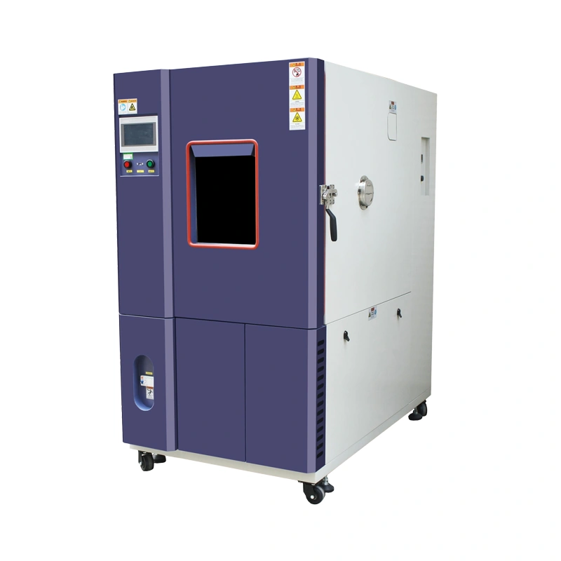
Key Technical Specifications of a PCB Low Humidity Test Chamber
1. Humidity Range & Precision
-
Range: 1%–98% RH (critical: stable at 5%–10% RH) — essential for an ultra low humidity chamber for MSL PCB storage.
-
Accuracy: ±1% RH (at 10% RH);Uniformity: ±2% RH (empty chamber).
-
Why It Matters: Even ±3% RH fluctuation at 10% RH invalidates ESD and material brittleness test data.
2. Temperature Range & Stability
-
Range: -40°C~150°C (covers PCB operating/storage temps) — critical for a low humidity temperature cycling chamber for electronics.
-
Accuracy: ±0.1°C;Uniformity: ±1.0°C.
-
Critical Pairing: Low humidity + temperature cycling (e.g., -40°C/10% RH → 85°C/85% RH) simulates real-world extreme conditions.
3. Dehumidification Technology (Core Differentiator)
-
Dual-Evaporator Dehumidification: One evaporator for cooling, one for dehumidification; prevents frost, maintains ±1% RH stability at 5%–10% RH.
-
Desiccant-Assisted Dehumidification: Combines molecular sieve desiccant with refrigeration; achieves 1%–5% RH (ultra-low humidity) for MSL 5/5a components.
4. Chamber Volume & Load Capacity
-
R&D Prototypes: 30L–50L (accommodates 10–20 small PCBs, e.g., wearables, sensors) — ideal for a compact low humidity test chamber.
-
Production Batch Testing: 100L–500L (holds 50–200 medium PCBs, e.g., motherboards, industrial control boards).
-
Key Note: Internal dimensions must allow 10–20mm spacing between PCBs for uniform airflow and humidity distribution.
5. Control System & Data Logging
-
Programmable Controller: Supports custom temperature-humidity profiles (cycling, constant);PID algorithm for real-time adjustment — a must for anyenvironmental test chamber for PCB circuit board.
-
Data Logging: Records temp/RH data every 1–5s; exports CSV/Excel reports for compliance audits.
-
Alarms: Over-temp, over-humidity, door open, power failure alerts.
6. Construction & Materials
-
Inner Chamber: SUS304 stainless steel (corrosion-resistant, easy to clean) — standard for high-quality PCB low humidity test chamber models.
-
Insulation: 50–80mm polyurethane foam (prevents condensation, energy efficiency).
-
Door Seal: Double-layer silicone rubber (airtight, prevents external moisture ingress).
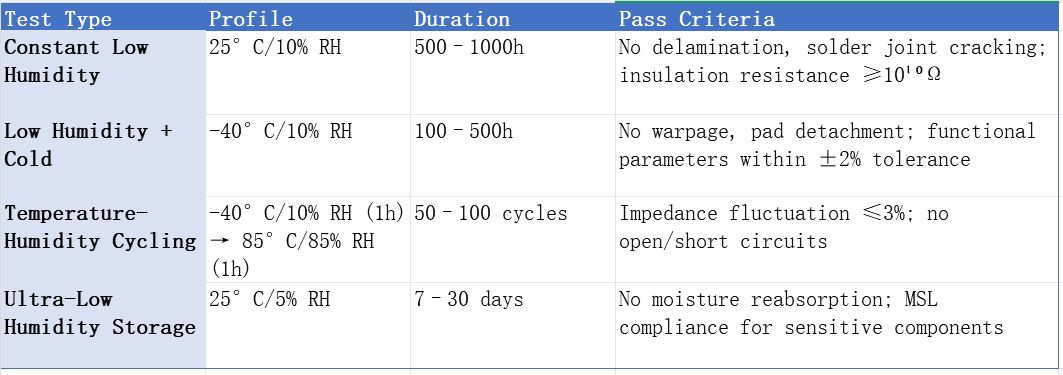
Common PCB Low Humidity Test Profiles & Pass Criteria
|
Test Type
|
Profile
|
Duration
|
Pass Criteria
|
|---|---|---|---|
|
Constant Low Humidity
|
25°C/10% RH
|
500–1000h
|
No delamination, solder joint cracking; insulation resistance ≥10¹⁰Ω
|
|
Low Humidity + Cold
|
-40°C/10% RH
|
100–500h
|
No warpage, pad detachment; functional parameters within ±2% tolerance
|
|
Temperature-Humidity Cycling
|
-40°C/10% RH (1h) → 85°C/85% RH (1h)
|
50–100 cycles
|
Impedance fluctuation ≤3%; no open/short circuits
|
|
Ultra-Low Humidity Storage
|
25°C/5% RH
|
7–30 days
|
No moisture reabsorption; MSL compliance for sensitive components
|
How to Select the Right Low Humidity Test Chamber for PCB Testing
Step 1: Define Your Testing Requirements
-
Application: Consumer electronics (IPC-TM-650) vs. automotive (AEC-Q200) vs. aerospace (custom specs) — determines if you need an AEC-Q200 circuit board humidity test chamber or standard model.
-
Sample Size: R&D (small volume) vs. production (batch testing) — impacts chamber volume selection.
-
Humidity Target: Standard low (5%–10% RH) vs. ultra-low (1%–5% RH) — decides if you need an ultra low humidity chamber for MSL PCB storage.
Step 2: Verify Core Performance Specs
-
Humidity Stability: Reject chambers with >±2% RH fluctuation at 10% RH — critical for reliable PCB low humidity test chamber performance.
-
Dehumidification Speed: Should reach 10% RH from ambient (60% RH) in ≤30min.
-
Uniformity: Ensure ±2% RH across the entire working volume (critical for batch testing).
Step 3: Evaluate Compliance & Support
-
Certifications: ISO 9001, CE, RoHS; calibration traceable to national standards — non-negotiable for a compliant low humidity test chamber.
-
After-Sales Support: 24/7 technical support, on-site installation/training, 1–2 year warranty, spare parts availability.
-
Customization: Ability to modify chamber size, add ESD monitoring, or integrate with production lines — ideal for specialized environmental test chamber for PCB circuit board needs.
Step 4: Calculate TCO
-
Initial Cost: Balance budget with performance (avoid cheap chambers with unstable low humidity).
-
Energy Consumption: Dual-evaporator systems are 20–30% more energy-efficient than single-evaporator models — reduces long-term costs for your low humidity test chamber.
-
Maintenance Cost: SUS304 construction reduces corrosion maintenance; desiccant replacement every 6–12 months.
Why Partner with a Professional Manufacturer for Low Humidity Test Chambers
-
Engineer-Designed Systems: Dual-evaporator/desiccant dehumidification optimized for 5%–10% RH stability — perfect for a high-performance PCB low humidity test chamber.
-
PCB-Specific Testing Expertise: In-depth knowledge of IPC/AEC standards to help design compliant test profiles.
-
Custom Solutions: Tailored chamber sizes, ESD monitoring integration, and automation for production lines — ideal for specialized low humidity temperature cycling chamber for electronics needs.
-
Full Lifecycle Support: From installation and training to calibration and maintenance, ensuring consistent test results for years.
Take the Next Step: Optimize Your PCB Testing Workflow
-
Get a customized chamber recommendation based on your test requirements and budget — whether you need an AEC-Q200 circuit board humidity test chamber or standard model.
-
Receive a free technical consultation on test profile design and compliance.
-
Request a detailed quotation with full specs and TCO analysis.
