
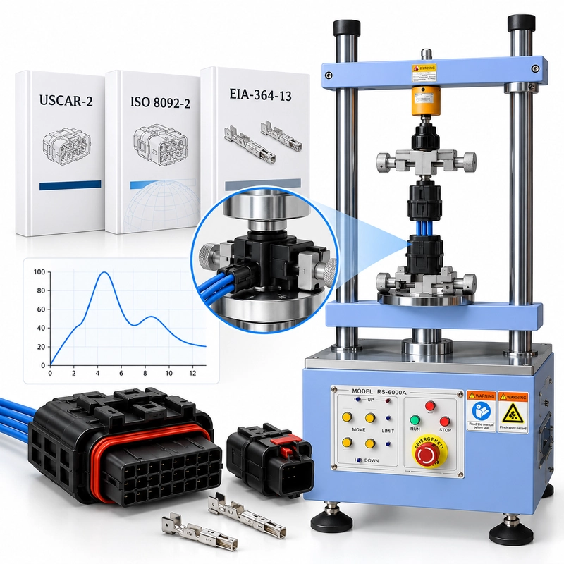
A 24-way sealed automotive connector reaches 68 N during mating. Another lab tests the same part number and reports 81 N.
Which result is right?
Before blaming the connector—or either test machine—look at the test itself.
Were both samples populated with the same terminals? Were the seals installed? Was the latch state the same? Were the connector axes actually aligned? Did both labs use the same speed and mating endpoint?
“Mating force” sounds like one measurement. In practice, it is the mechanical response of an entire connector system under a defined set of conditions.
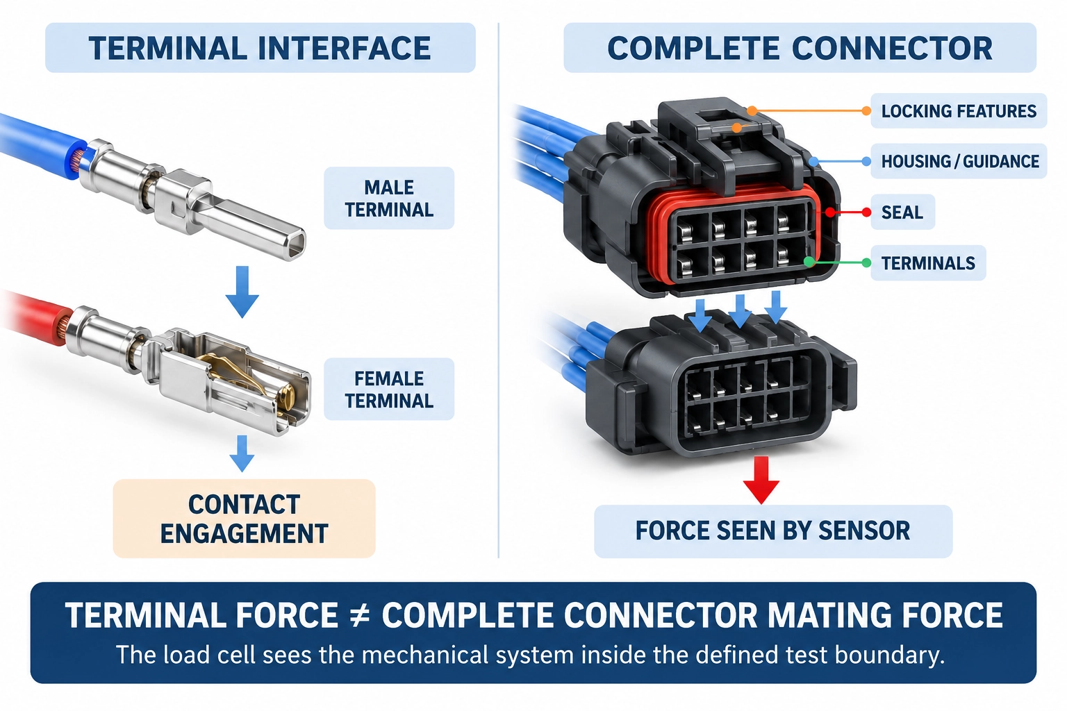
For a complete automotive connector, the load cell may see terminal engagement, seal compression, housing guidance, friction and locking features. If the setup is poor, it may also see fixture-induced side load.
That leads to the question that matters throughout this guide:
What exactly did you measure?
This article focuses on connector-to-connector automotive connector mating force and unmating force. It does not cover wire harness pull, crimp pull-out or cable tensile testing.
What Are You Actually Measuring?
Put one connector half in the stationary fixture and the other in the moving fixture. The tester brings them together along the intended mating axis.
What reaches the load cell?
Not just contact force.
Depending on the connector design, the measured load can include terminal engagement, interface-seal compression, housing guidance, friction between mating surfaces and resistance associated with locking features.
That is why “connector insertion force” can become misleading when the specimen is not clearly defined.
An individual terminal pair is one mechanical interface. A fully assembled sealed connector is a mechanical system.
The current SAE specification is USCAR2-9, revised December 6, 2024. Its scope covers performance testing of electrical terminals, connectors and related connection-system components for specified road-vehicle applications, including in-line, header and device connector systems. SAE Mobilus
The practical point is simple:
Describe the configuration that produced the force—not just the force value.
Terminal Force Is Only Part of the Story
Suppose a 32-way connector is fully populated.
If one terminal pair requires a certain engagement force, can you multiply that number by 32 and predict the complete connector mating force?
Not reliably.
That shortcut ignores how the connector actually mates.
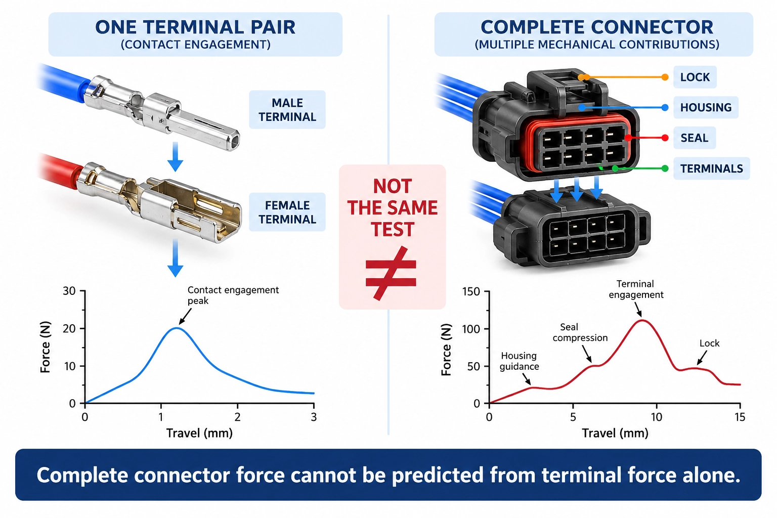
Individual contacts do not necessarily reach their maximum resistance at exactly the same travel position. A seal may already be compressing while terminals begin engaging. Housing guidance can contribute elsewhere in the stroke. A locking feature may create another mechanical event near final mating.
Tolerance matters too.
So:
Complete connector mating force is a system response, not simply terminal force × terminal count.
This distinction becomes particularly important when comparing connectors from the same family.
A 32-cavity housing populated with 20 terminals is not mechanically equivalent to the same housing populated with all 32.
Record both:
Cavity count: 32
Terminal population: 20
Those numbers describe different things.
Define the Test Article Before You Define the Machine
This is where details that look like paperwork begin affecting the result.
For a meaningful comparison, the test article has to be defined well enough that another engineer can reproduce it.
At minimum, that usually means knowing the housing, cavity count, actual terminal population, sealing configuration, secondary components, lock condition and any required preconditioning.
For example:
Housing: 24-way
Terminal population: 24/24
Interface seal: Installed
TPA / wedge: Installed where applicable
CPA condition: Defined by the procedure
Cycle condition: Recorded
Now compare that with a report that simply says:
“24-pin automotive connector — 68 N”
The second result is much harder to reproduce.
This also matters when the same housing is used in several production variants. Two parts may share the same outer shell but not the same mechanical mating system.
The applicable controlled standard, connector drawing and OEM/customer procedure should define the actual specimen condition.
Mating, Unmating, Unlocking and Retention Are Different Tests
Several automotive connector tests involve force along or near the mating axis. They are still different mechanical events.
| Test | Mechanical event | What it tells you |
|---|---|---|
| Mating Force | Connector halves move together | Force required to reach the defined mated condition |
| Unmating Force | Connector halves separate under the defined release condition | Resistance during connector separation |
| Unlocking Force | A release feature is operated | Force required to operate the locking mechanism |
| Retention Force | A locked connection is mechanically loaded | Ability of the locked assembly to resist separation |
| Terminal Engage / Disengage | Individual terminal pair moves together or apart | Mechanical behavior of the terminal interface |
This guide concentrates on mating and unmating.
There is another boundary worth making explicit:
Automotive connector unmating force is not wire harness pull force.
Separating two connector housings along their mating axis evaluates the connector interface. Pulling a wire relative to its terminal, crimp or housing changes the load path and answers a different engineering question.
The unit may still be newtons.
The test is not the same.
Locked or Released? It Changes the Test
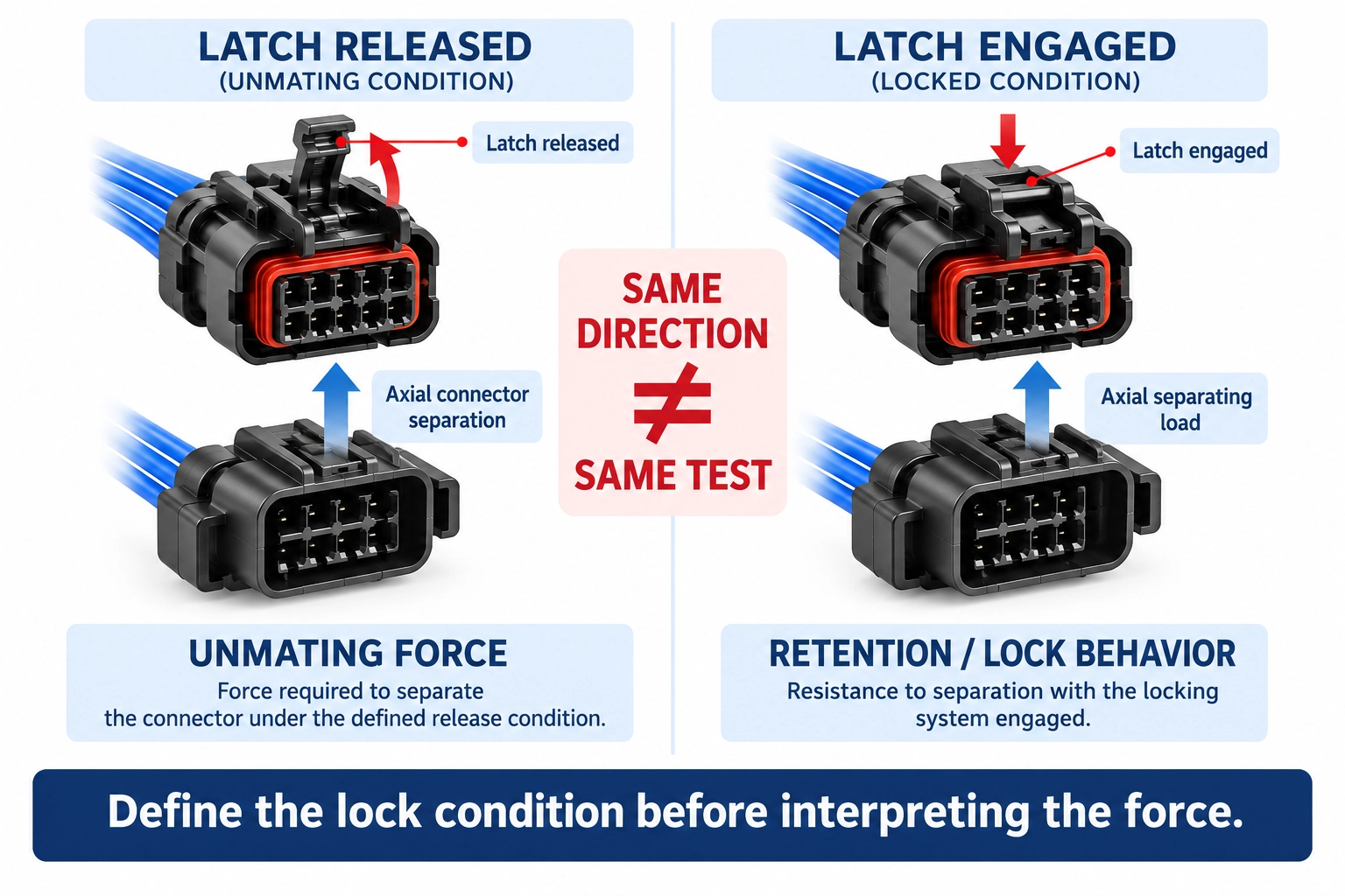
Imagine the same connector pair mounted in the same force tester.
In the first test, the primary latch is released before separation.
In the second, the latch remains engaged while the machine applies an axial separating load.
The crosshead may move in the same direction, but the mechanical events are different.
The first can represent the defined unmating operation.
In the second, the locking system resists separation. Depending on the procedure, you may now be evaluating retention or lock behavior rather than ordinary unmating force.
CPA and secondary locking features introduce the same issue.
Their state should not be left to whoever happens to install the specimen that day.
Define it. Record it.
One rule is worth keeping:
Never transfer a force limit from one mechanical event to another simply because both values are reported in newtons.
Sealed Connectors Add Another Mechanical System
A sealed automotive connector does not simply add “a little more friction.”
The sealing system can become a meaningful part of the force-travel response.
As the connector mates, housing guidance, seal contact, seal compression, terminal engagement and final locking can occur at different—and sometimes overlapping—positions in the stroke.
That makes curve interpretation useful, but it also creates a trap.
It is tempting to point to a feature on the trace and say:
“That peak is the seal.”
Maybe.
But the curve alone does not prove it.
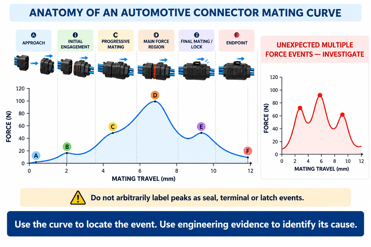
A force-travel trace can tell you where in the mating travel a mechanical event occurred. Identifying its physical cause requires supporting evidence from connector geometry, controlled sample changes, observation or another diagnostic method.
That distinction matters in failure analysis.
Use the curve to locate the event. Do not use it to invent the cause.
Test Speed Is Part of the Test Condition
Speed is sometimes treated as a machine setting that disappears once the test starts.
It should remain part of the result context.
If two laboratories test the same part at materially different speeds, a difference in measured force should not immediately be attributed to product variation.
The first question is whether they reproduced the same procedure.
This is especially important when comparing:
a supplier report,
an internal laboratory result,
a qualification test,
and a production-line investigation.
A useful rule is:
A force value without its test speed is missing part of its test condition.
Do not copy a speed from another connector family simply because the equipment can reproduce it. Use the speed required by the applicable controlled standard or OEM/customer procedure.
The Curve Knows Something the Peak Doesn't
Peak force is useful.
It is also a highly compressed description of a mechanical event.
Consider two connector samples. Both produce an illustrative maximum mating force of 68 N.
The first curve rises progressively, reaches its maximum within the expected mating region and continues toward the defined endpoint.
The second reaches 68 N very early in travel, drops and then continues mating.
If your report stores only:
Maximum Force = 68 N
the samples look identical.
Mechanically, they are not.
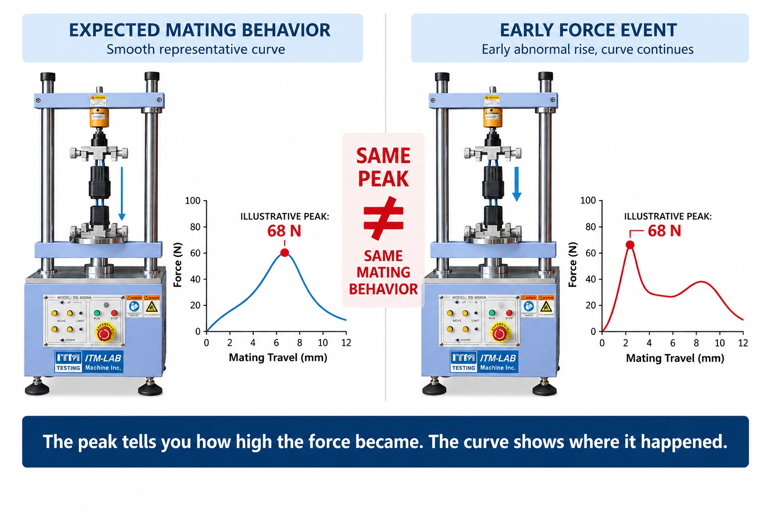
The 68 N value is an illustrative example, not an automotive connector acceptance limit.
Reading the Mating Curve
Instead of thinking of the horizontal axis only as millimeters, treat it as a timeline of the mating event.
A — Approach: The connector halves move toward their first meaningful mechanical interaction.
B — Initial Engagement: Housing or guidance features begin interacting. Fixture offset can already influence the result here.
C — Progressive Mating: More of the connector system contributes to the measured resistance. Terminal, seal and housing interactions may overlap.
D — Main Force Region: The primary force event occurs. Both its magnitude and travel position can be useful.
E — Final Mating / Lock Region: The connector approaches its defined final condition.
F — Endpoint: The test stops where the specified mating operation is complete.
Do not keep driving simply because the tester has more stroke available.
Alignment Errors Become Measured Force
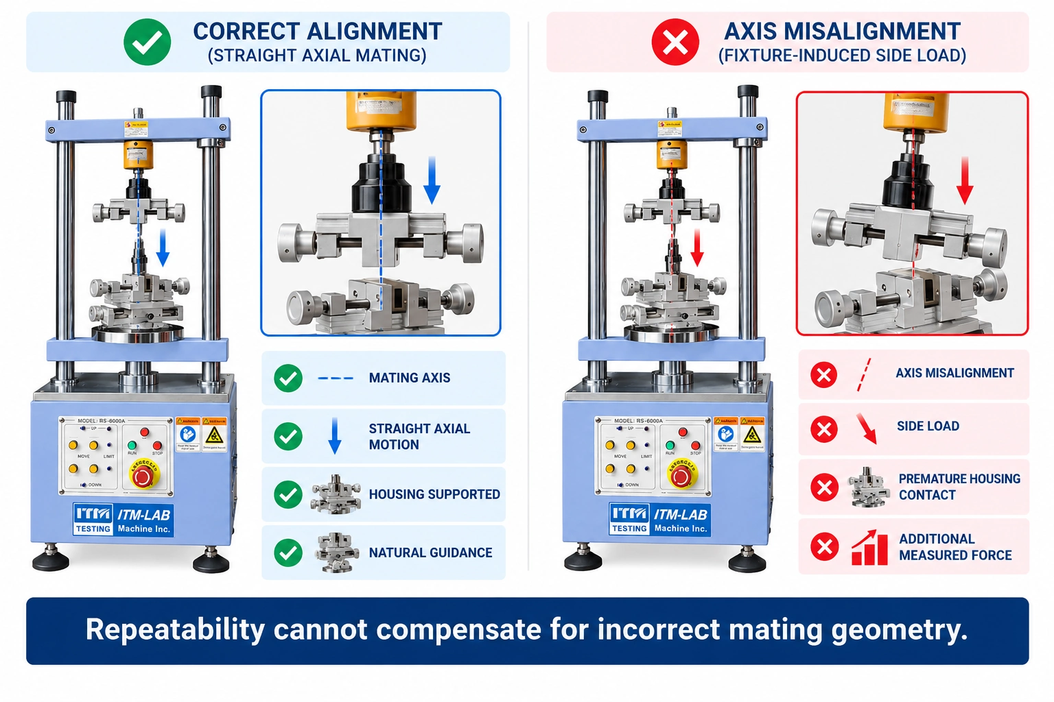
The machine moves in a straight line.
The connector halves are slightly misaligned.
As mating begins, the connector geometry tries to accommodate the mismatch. That can create side load, premature housing contact, additional friction, fixture deflection or binding.
The load cell measures the resulting force.
It cannot automatically separate “real connector force” from “force created by bad alignment.”
That leads to an important practical point:
A repeatable fixture can produce a repeatably wrong result.
Five nearly identical curves demonstrate repeatability.
They do not prove correct mating geometry.
A Good Fixture Has Three Jobs
A connector fixture does not need to look complicated. It needs to control the right things.
Hold: Keep the specimen secure without unwanted movement.
Align: Establish the intended mating axis.
Stay out of the test: Do not deform the housing, obstruct natural guidance, contact moving features or become an unintended mechanical stop.
The fixture also depends on connector architecture. An in-line connector, a header and a device connector can require very different support geometry.
Current USCAR2-9 explicitly covers applicable terminals used in in-line, header and device connector systems. SAE Mobilus
Practical note: If an unexpected force peak appears near the beginning of travel, check alignment and unintended housing contact before changing the load-cell range or concluding that the terminal system is defective.
Can You Predict Mating Force From Terminal Count?
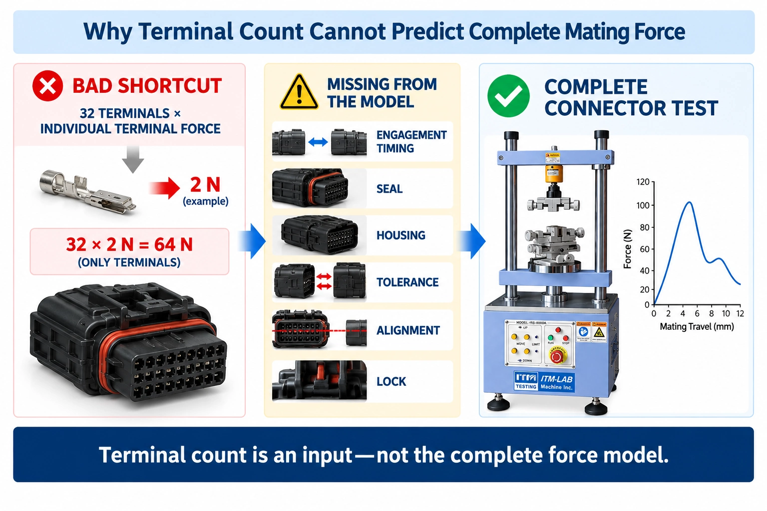
A tempting shortcut looks like this:
32 terminals × 2 N = 64 N connector mating force
It is tidy.
It is also incomplete.
The calculation ignores engagement timing, seals, housing guidance, tolerance stack, alignment and locking features. Individual mechanical contributions may also peak at different travel positions.
Terminal count remains useful information.
So does actual terminal population.
Neither is a complete force model.
A High Reading Doesn't Always Mean a Bad Connector
Illustrative troubleshooting example
A sealed 32-way connector produces a mating-force trace that looks higher than expected.
The first reaction might be:
“The terminals are too tight.”
That conclusion is premature.
First, confirm the specimen.
Is the terminal population the same as the reference sample? Is the interface seal installed? Are the specified secondary components present? Has the sample seen the same preconditioning or mating cycles?
Then look at the curve.
Suppose the unexpected force event occurs near the beginning of travel rather than in the normal main mating region.
That gives you somewhere to investigate.
Inspection of the fixture reveals a small angular offset between the two connector halves. After the alignment is corrected and the test repeated, the early abnormal feature disappears and the mating trace becomes smoother.
That does not automatically mean the connector passes.
The resulting force still has to be evaluated against the applicable requirement.
What improved was the quality of the measurement.
The test is now closer to the intended mechanical event.
When troubleshooting, this question is often more useful:
Where in the travel did the force change?
than:
How many newtons too high is it?
Where Does the “75 N Connector Force Limit” Actually Apply?
Search for automotive connector force limits and 75 N appears frequently.
Do not put that number on a drawing simply because it appeared in a search result.
Mating force, unmating force, unlocking force and retention are different mechanical requirements. Their acceptance criteria can depend on the applicable standard, revision, connector design and OEM/customer specification.
Current USCAR2-9 should therefore be used as a controlled specification rather than reduced to a context-free “automotive connector force limit.” SAE currently identifies USCAR2-9 as the current revision, with a December 2024 revision date. SAE Mobilus
A better sequence is:
Which mechanical event?
↓
Which connector configuration?
↓
Which standard and revision?
↓
Which OEM/customer requirement?
↓
Which acceptance criterion applies?
A number can be correct for one test and completely inappropriate for another.
Which Standards Matter?
For this application, four references or requirement layers are worth separating.
| Reference | Relevance to the test |
|---|---|
| SAE/USCAR-2 | Automotive electrical connector-system performance testing and requirements |
| ISO 8092-2:2023 | Terminology, test methods and general performance requirements for voltage Class A connectors used in road-vehicle wiring harnesses |
| EIA/ECA-364-13 | General mating and unmating force test procedure for electrical connectors and sockets |
| OEM / Customer Specification | May define the actual configuration, conditioning, test parameters and acceptance criteria for the project |
SAE currently lists USCAR2-9 as the current revision, dated December 6, 2024. Its published scope includes applicable low-voltage 0–60 VDC and coaxial road-vehicle connection systems. SAE Mobilus
ISO currently lists ISO 8092-2:2023, Edition 5, published in September 2023. It covers terminology and general performance test methods for voltage Class A connectors used in road-vehicle electrical wiring harnesses, within the scope defined by ISO. ISO
The U.S. DLA ASSIST database lists EIA/ECA-364-13 as active and identifies it as Mating and Unmating Forces Test Procedure for Electrical Connectors and Sockets. ASSIST-QuickSearch
For qualification work, use the applicable controlled standard and customer documentation rather than relying on a summary article—including this one—for acceptance criteria.
Why Can Two Labs Get Different Results?
When two laboratories disagree, do not start by comparing only the final peak values.
First compare the test conditions.
Were the housing, terminal population, seals and secondary components the same? Had the specimens seen the same conditioning or mating cycles? Was the speed identical? Was the latch or CPA in the same state? Were the mating axes aligned? Did both fixtures support the housing in the same way? Did both tests stop at the same endpoint?
Then look at data processing.
Did both systems define the reported maximum over the same part of the stroke?
Only after those variables are controlled does a machine-to-machine comparison become particularly useful.
A calibration certificate answers an important question:
Can this measurement system measure force correctly?
It does not answer:
Did both laboratories perform mechanically equivalent tests?
You need both.
What Should the Test Report Preserve?
For routine production screening, a peak value and pass/fail result may be enough.
For development, supplier comparison or failure analysis, keep enough information to reproduce the test.
A useful record includes:
Connector part number | cavity count | terminal population | seal condition | mating/unmating | latch/CPA state | standard + revision | test speed | mating endpoint | fixture configuration | cycle/conditioning state | peak force | force-travel curve
The principle is more important than the exact template:
A force result without its mechanical test condition becomes difficult to compare later.
What the Test System Actually Needs to Control
Do not start equipment selection with:
“How many kilograms is the machine?”
Start with the connector.
The measurement range should suit the expected working force. The motion system must reproduce the intended mating direction and required speed. The available test space has to accommodate the fixtures, connector halves, loading clearance and complete mating travel.
And the fixture has to hold the specimen without becoming part of the result.
Force-travel synchronization matters too. Peak force can support a pass/fail decision; synchronized force and displacement provide much more information when the goal is to understand where an event occurred.
For ITM-LAB applications, these requirements can be configured around the RS-6600A Automatic Insertion and Extraction Force Tester, with 5–100 kgf force configurations, 150 mm travel, speeds up to 600 mm/min, Class 0.5 accuracy, Panasonic servo control and synchronized force-displacement acquisition.
The capacity figure alone, however, does not determine whether the system is right for a connector.
Working force, usable test envelope, speed, fixture geometry and alignment come first.
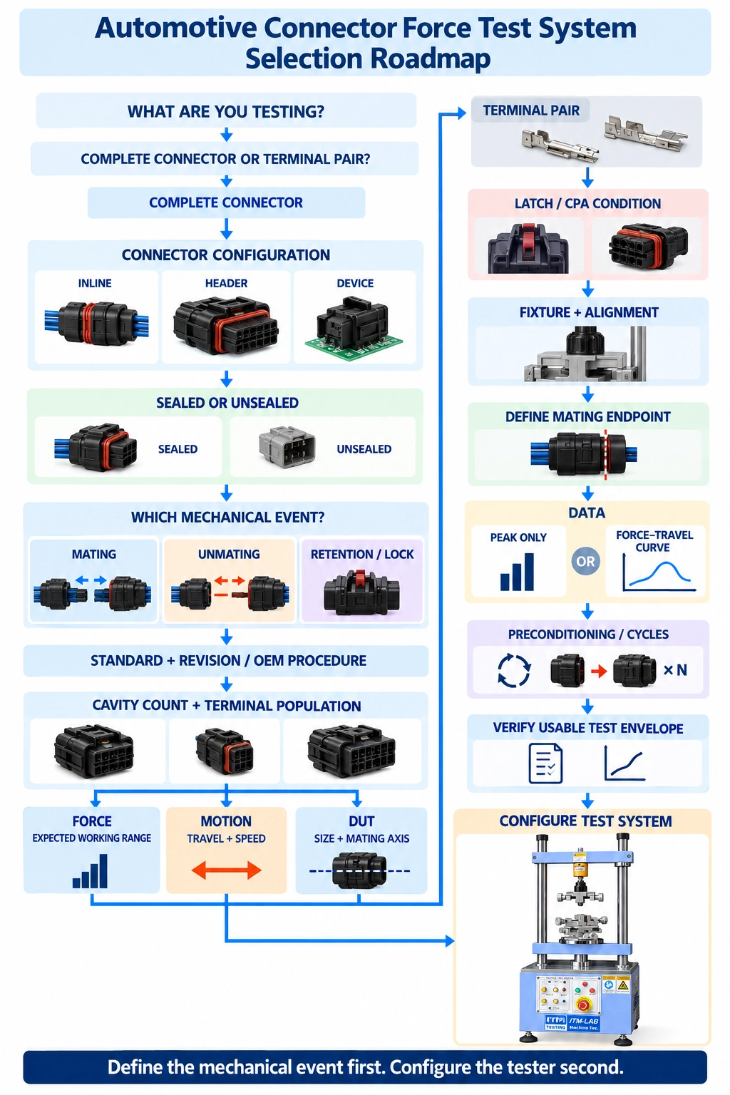
Automotive Connector Force Test System Selection Roadmap
What We Need to Configure the Test
A first technical review does not require a long RFQ.
Send us the connector drawing or mating pair, along with the cavity count and terminal population, sealed/unsealed configuration, required mating or unmating measurement, expected force range, travel, speed, lock/CPA condition, applicable standard and revision, and whether you need peak force only or the complete force-travel curve.
That is usually enough to start reviewing the test envelope and fixture approach.
FAQ
What is automotive connector mating force?
Automotive connector mating force is the force measured while defined connector halves are brought together under specified mechanical conditions. For a complete connector, the result can include terminal engagement, seals, housing guidance and locking features within the defined mating operation.
What is the difference between mating and unmating force?
Mating force is measured while connector halves move together. Unmating force is measured during their defined separation. Lock and release conditions must be specified because pulling apart a locked connector can represent a different mechanical test.
Is 75 N the maximum automotive connector mating force?
Do not treat 75 N as a universal mating-force limit. Determine the mechanical event, applicable standard and revision, connector configuration and OEM/customer requirement before applying an acceptance criterion.
Does terminal count determine automotive connector mating force?
No. Terminal population contributes to the result, but seals, housing geometry, engagement timing, tolerance, alignment and locking features can also affect the complete connector response.
Why is my connector mating force higher than expected?
Check specimen configuration, seal condition, conditioning history, test speed, fixture alignment, lock state and mating endpoint before concluding that the connector itself is defective. The location of the abnormal event on the force-travel curve can help narrow the investigation.
Should I record peak force or the complete force-travel curve?
Peak force may be sufficient for some production decisions. A synchronized force-travel curve is more useful for engineering analysis because it shows where mechanical events occur during the mating stroke.
Final Takeaway
When an automotive connector produces an unexpected force result, the first question should not be:
Is the number too high?
Ask:
What exactly did we measure?
Was the connector in the correct configuration? Were the seals and required secondary components installed? Was the lock state defined? Did the two halves move along the intended mating axis? Was the correct speed used? Did the test stop at the intended endpoint?
Once those conditions are controlled, the peak force becomes much more meaningful.
And when two samples reach the same peak, look at the curve.
The number tells you how high the force became. The force-travel history tells you when it happened.
That is often where the useful engineering investigation begins.
