
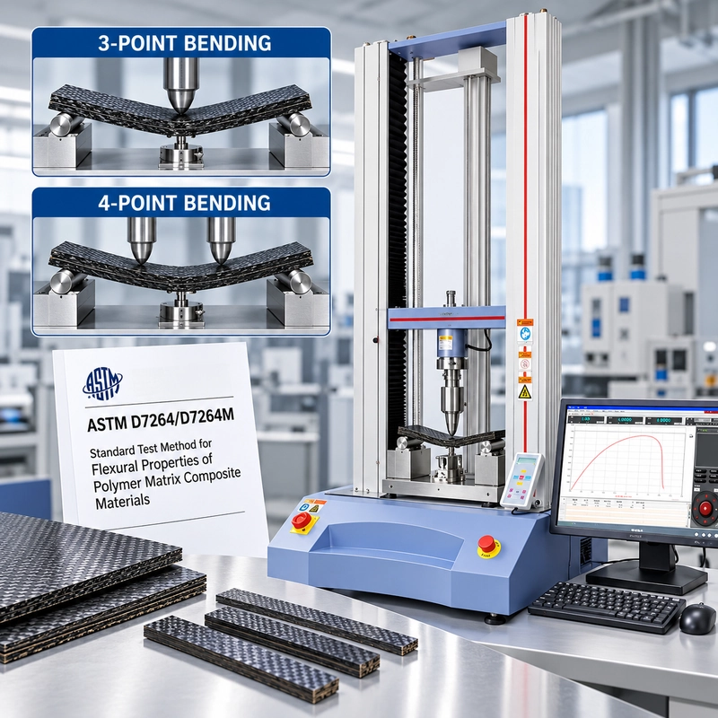
Two CFRP coupons come from the same laminate panel. Both are 4 mm thick.
One is tested over a 64 mm support span. The other over 128 mm.
Same material. Same thickness. Same universal testing machine.
Should the reported flexural strength be the same?
Not necessarily.
In ASTM D7264 composite flexural testing, span is part of the test—not just a fixture setting. Change the loading geometry or span-to-thickness relationship and you change the stress state inside the coupon. Change how deflection is measured and you may change the stiffness result. Ignore where the specimen actually failed and a perfectly clean peak on the force curve can become misleading.
That is why setting up ASTM D7264 starts with the coupon, not the machine.
ASTM D7264/D7264M covers flexural properties of polymer matrix composites, particularly continuous-fiber-reinforced materials. The current ASTM D7264/D7264M-26 includes two configurations: Procedure A uses three-point loading and Procedure B uses four-point loading. A standard 32:1 span-to-thickness ratio is used, which is one of the important differences between this method and common plastics flexural methods such as ASTM D790 and ASTM D6272.
This guide focuses on what those requirements mean at the test bench: how the loading method changes specimen response, why 32:1 matters, what failure location can tell you, where the deflection number comes from, and how to turn coupon requirements into a practical UTM and fixture configuration.
What Is Actually Happening Inside the Laminate?
A flexural test looks simple from outside the fixture.
The coupon sits on two supports. The crosshead moves. The specimen bends.
Inside the laminate, the situation is more complicated.
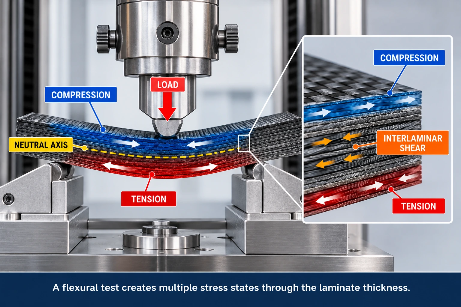
As the beam bends, one outer surface is placed primarily in compression while the opposite surface is placed primarily in tension. Between them lies the neutral axis. Transverse shear stresses also develop through the thickness.
For a homogeneous material, beam theory gives us a convenient way to describe this stress distribution. For a laminated composite, however, the material itself is directional and layered.
Fibers may carry most of the longitudinal load. The matrix transfers stress and supports the reinforcement. Interfaces between plies introduce another possible damage path.
So the coupon does not have only one way to fail.
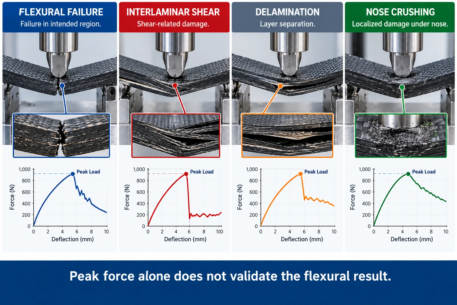
A CFRP specimen might develop tensile fiber fracture on one face, compression damage on the other, delamination between plies, or shear-related damage through the laminate. Local contact beneath the loading nose can introduce another failure mechanism entirely.
That is the first reason why the highest force recorded by the UTM should never be interpreted in isolation.
ASTM D7264 Procedure A vs Procedure B
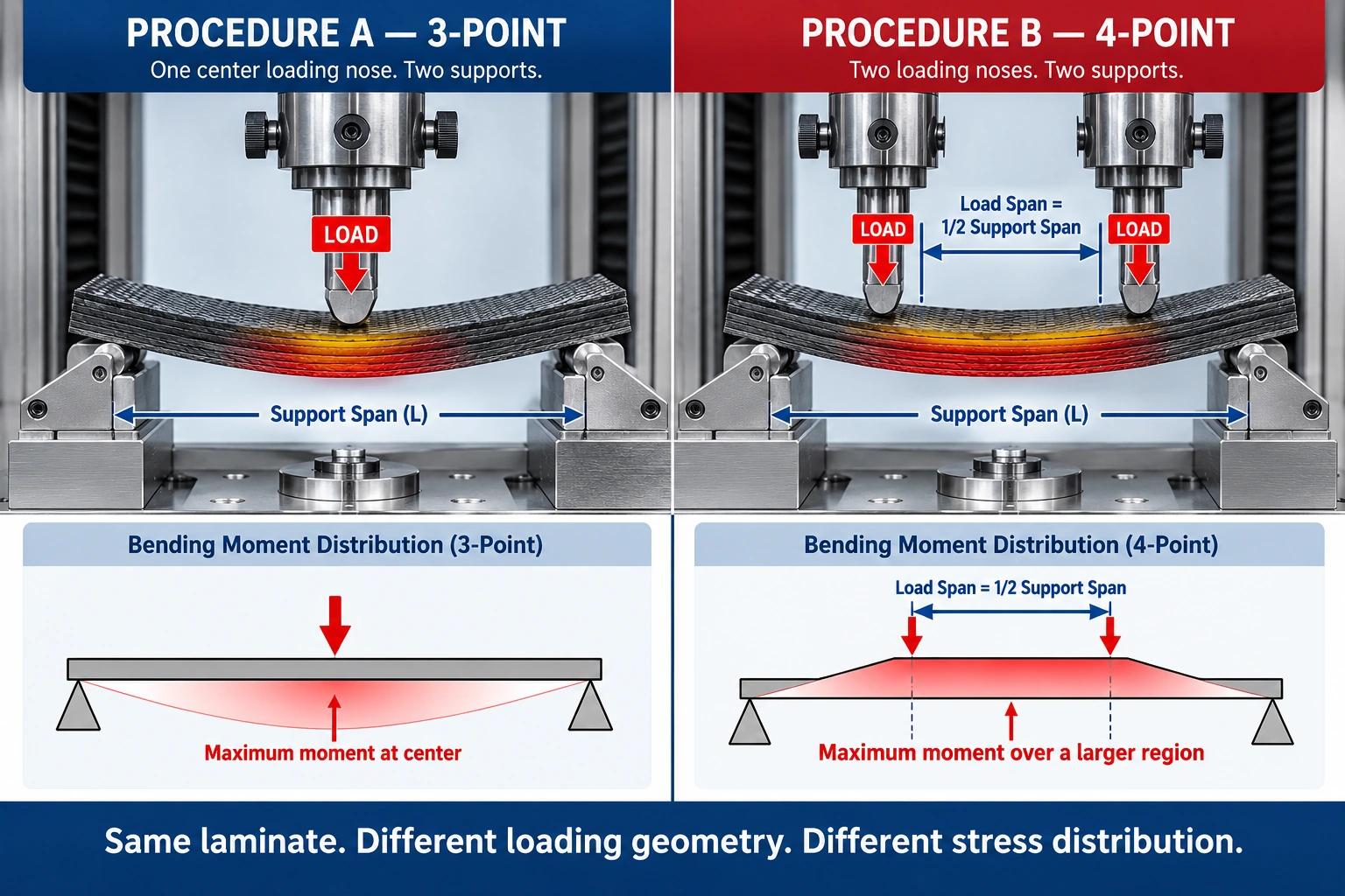
ASTM D7264 gives the laboratory two loading arrangements.
Procedure A is three-point bending.
The specimen is supported at two points and loaded by one nose at the center of the span.
Procedure B is four-point bending.
The specimen again sits on two outer supports, but force is introduced through two loading noses. For D7264, the distance between those loading points is one-half of the support span.
They are not simply two fixture styles for obtaining the same number.
Three-point bending concentrates the maximum moment
With a single center loading nose, the maximum bending moment occurs at the center.
That means the most highly stressed region is strongly localized around one position.
If the laminate's weakest significant defect is somewhere else along the coupon, that defect may never experience the same maximum bending moment.
Four-point bending exposes a larger region
Between the two loading noses in the four-point configuration, the specimen experiences a region of maximum bending moment.
That exposes a larger length of material to the most severe bending condition.
For composite materials, that difference matters.
Voids, local fiber waviness, resin-rich areas, ply defects and other material variations do not conveniently occur at the exact center of every coupon. A larger highly stressed region gives defects over a larger portion of the specimen an opportunity to influence failure.
That does not make Procedure B inherently "better."
It makes it different.
ASTM notes that Procedure A and Procedure B can produce slightly different property values. When results are being compared, the same procedure should therefore be used throughout the comparison.
If a customer drawing specifies Procedure A, use Procedure A.
If an internal R&D program has a choice, document the selected procedure and keep it consistent between materials, batches and conditioning groups.
The 32:1 Ratio Is Doing a Job
For the standard ASTM D7264 configuration:
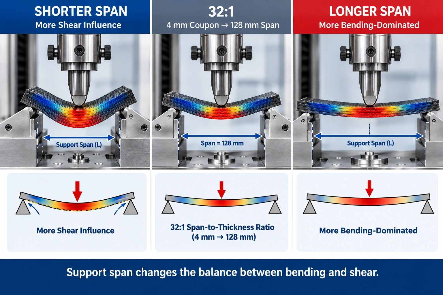
Support Span / Specimen Thickness = 32:1
or:
L = 32h
where:
L = support span
h = specimen thickness
ASTM identifies this 32:1 ratio as one of the distinctions between D7264 and ASTM D790/D6272, where a standard 16:1 span-to-thickness ratio is used. D7264 is intended to evaluate long-beam flexural behavior, whereas ASTM D2344/D2344M addresses short-beam strength.
Why does that matter?
Because bending and shear do not contribute equally at every span.
Reduce the span relative to specimen thickness and transverse shear becomes more significant. Increase the relative span and the response becomes more bending dominated.
This is particularly important with laminated composites because an interlaminar shear failure can occur before the outer fibers reach the flexural condition the test was intended to investigate.
So when an operator adjusts the supports, that adjustment is not merely making the coupon fit.
It is defining part of the mechanical test condition.
A quick example
For a 2 mm laminate:
32 × 2 = 64 mm
For a 4 mm laminate:
32 × 4 = 128 mm
For a 6 mm laminate:
32 × 6 = 192 mm
That simple progression also tells us something about equipment selection.
If a laboratory plans to test coupons from 2 to 6 mm thick, the bending fixture needs to accommodate the corresponding support spans. A fixture that physically stops at 100 mm may be perfectly usable for the 2 mm specimen and unsuitable for the 4 mm and 6 mm specimens under the same 32:1 condition.
If a supplier only receives:
"We need an ASTM D7264 fixture."
there still is not enough information to configure the fixture correctly.
At minimum, we want to know what specimens are going into it.
A 4 mm CFRP Coupon: Worked Example
Consider a rectangular CFRP coupon tested using Procedure A.
For illustration, assume:
Width, b = 13.0 mm
Thickness, h = 4.00 mm
Support span, L = 128 mm
Peak load, P = 1,200 N
For a rectangular specimen in three-point bending, the outer-surface flexural stress relationship takes the familiar form:
σf = 3PL / 2bh²
Substituting the example values:
σf = (3 × 1,200 × 128) / (2 × 13 × 4²)
which gives approximately:
σf = 1,108 MPa
or:
1.11 GPa
That number is useful, but the calculation reveals something else that is easy to overlook.
Look at the denominator:
h²
Thickness is squared.
Now suppose the actual specimen is 4.00 mm thick, but 4.10 mm is entered into the calculation.
Everything else stays the same.
Using 4.10 mm:
σf ≈ 1,054 MPa
The reported stress has moved from approximately:
1,108 MPa → 1,054 MPa
a difference of about 4.9%.
Nothing changed in the machine.
Nothing changed in peak force.
Nothing changed in the laminate.
Only the thickness value changed by 0.10 mm.
That is why we would not build a D7264 report around nominal drawing thickness alone. Measure the coupon as required by the method and keep the dimensional measurement practice consistent across the comparison.
For thin composite laminates, specimen metrology is part of the mechanical test.
Fiber Direction Can Change the Answer Before the Test Starts
Two coupons can have identical external dimensions and still represent very different material systems mechanically.
Consider a unidirectional laminate.
A specimen cut primarily along the fiber direction and one cut transverse to it do not carry flexural load in the same way.
The same issue appears with more complex layups.
A [0°]-dominated laminate, a [90°]-dominated laminate, a cross-ply construction and a quasi-isotropic laminate should not be treated as interchangeable simply because all four coupons are made from "CFRP."
This is why a useful composite test report should preserve enough information to identify what was actually tested.
Material designation alone may not be enough.
Depending on the program, useful information can include laminate construction, layup designation, specimen orientation relative to the panel, thickness, width, conditioning state, test procedure and support span.
If one batch was cut longitudinally and another transversely, excellent machine repeatability will not rescue a poor comparison.
If It Breaks Here, Ask Why
A clean peak on the force-deflection curve looks reassuring.
The broken coupon deserves at least as much attention.
Break in the intended high-bending region
Start by examining which surface initiated the failure and what the fracture looks like.
Tensile fiber fracture, compression damage and combinations of matrix and fiber failure can all appear depending on the laminate architecture.
A failure in the expected region does not automatically validate every aspect of the test, but it is much more informative than simply recording the maximum force.
Damage directly beneath a loading nose
Look closely at the contact zone.
If the laminate crushes locally under the nose before the intended flexural failure develops, the measured peak may be controlled by contact damage.
That is not the same question as:
"How strong is this laminate in flexure?"
A long split between plies
A visible split running along the laminate can indicate delamination or interlaminar involvement.
Ask whether the desired long-beam flexural response was reached before that damage became controlling.
Failure close to a support
Do not just save the peak load and move to the next coupon.
Check the span, specimen position, support contact, alignment and the specimen itself.
A recurring failure in the wrong place is information about the setup.
When the specimen breaks somewhere unexpected, investigate the location before interpreting the number.
When a Higher Peak Load Can Be a Worse Test
Imagine two nominally identical coupons.
Coupon A reaches:
1.20 kN
and fails in the intended high-bending region.
Coupon B reaches:
1.28 kN
but inspection shows severe localized crushing directly beneath the loading nose.
Which coupon demonstrated the higher valid flexural strength?
The answer cannot be established from 1.20 versus 1.28 kN alone.
Coupon B produced the larger machine reading. It also produced evidence that a different failure mechanism may have controlled that reading.
This distinction matters when test software automatically creates a report containing maximum force, maximum stress and pass/fail results.
A numerical report can be internally consistent and still omit the most important diagnostic observation from the test.
For composite flexure, save the curve.
But look at the coupon.
The Curve Has a Story Too
Failure inspection should not replace the force-deflection curve. The two belong together.
At the beginning of a test, a small seating region may appear as the specimen, supports and loading nose establish full contact.
The main rising portion of the curve reflects the structural response of the coupon and test system.
Departure from the expected linear response may indicate the onset of damage or nonlinear behavior.
A sharp load drop can accompany sudden fracture.
A more gradual post-peak reduction may occur as damage develops progressively.
Some laminates produce multiple load drops rather than one clean break because individual plies or interfaces can fail while the remaining structure continues carrying load.
This is useful diagnostic information.
If one group of coupons repeatedly produces a smooth, repeatable response while another shows early discontinuities and large scatter, the difference deserves investigation even if their average peak forces look similar.
The curve should therefore be treated as more than a route to one maximum value.
Where Did That Deflection Number Come From?
Open the test report and find the deflection column.
Before using it for a stiffness or modulus calculation, ask one question:
Where was it measured?
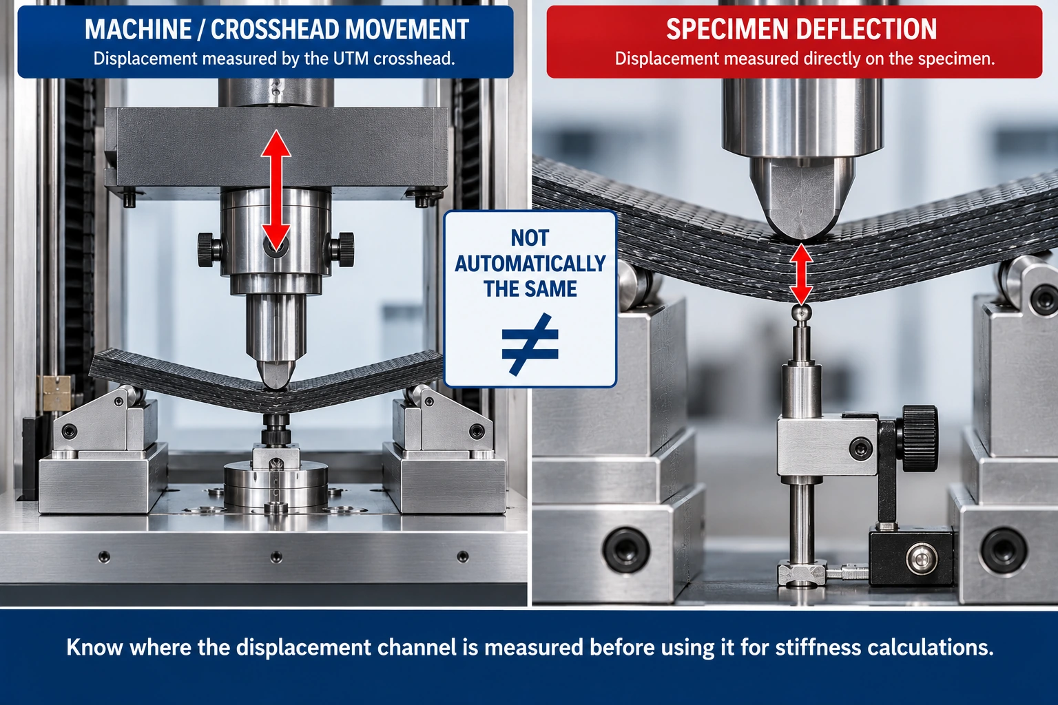
The UTM knows how far its moving crosshead or actuator has travelled.
That movement can contain more than specimen bending.
It can include contributions from machine compliance, fixture deformation, contact seating and the way the coupon rotates against the supports and loading nose.
A displacement measurement taken directly at the specimen is trying to answer a different question: how much did the specimen itself deflect at the defined measurement location?
Those numbers are not automatically identical.
This distinction may have little effect on a simple internal test whose only objective is to compare maximum force under a fixed setup.
It becomes much more important when the required result depends on the slope of the force-deflection response.
That is why "the machine has displacement measurement" is not a complete answer when configuring a flexural modulus test.
Every modern electromechanical UTM measures its own motion.
The engineering question is:
Which displacement does the calculation require?
When ASTM D7264 Results Don't Look Right
A rerun is useful only if the setup is already right. When the same abnormal behavior keeps appearing, use the pattern as diagnostic information.
| What You See | What to Check First |
|---|---|
| Strength is consistently lower than expected | Actual dimensions, support span, specimen orientation and failure mode |
| Premature delamination | Span/thickness relationship, laminate quality and edge condition |
| Crushing beneath the loading nose | Contact geometry, specimen surface and whether local contact is controlling failure |
| Modulus varies while peak force is relatively stable | Deflection channel, seating, thickness input and fixture/machine compliance |
| Large coupon-to-coupon scatter | Layup, fiber direction, panel location, thickness and specimen preparation |
| Initial movement before meaningful load develops | Seating, zeroing and fixture contact |
| Failure repeatedly occurs near a support | Span, positioning, alignment, contact and local defects |
| Procedure A and B give different values | Do not mix the two procedures in one direct comparison |
| D7264 result differs from D790 data | Confirm that two different test methods are not being treated as equivalent |
The last two points are especially important when laboratories inherit historical data.
A spreadsheet full of "flexural strength" values is not necessarily one comparable dataset.
You need to know how those values were produced.
ASTM D7264 vs D790 vs D6272 vs D2344
All four methods involve bending or beam-type loading. They are not interchangeable.
| Standard | Main Application | Loading | Key Difference |
|---|---|---|---|
| ASTM D7264/D7264M | Polymer matrix composites | 3-point or 4-point | Long-beam composite flexural properties; standard 32:1 span/thickness ratio |
| ASTM D790 | Plastics and insulating materials | 3-point | Plastics flexural properties; standard geometry commonly uses 16:1 |
| ASTM D6272 | Plastics | 4-point | Four-point plastics flexural testing |
| ASTM D2344/D2344M | Polymer matrix composites | Short-beam loading | Short-beam strength / interlaminar-sensitive response |
A bending fixture does not define the test method.
The same universal testing machine may be capable of running D7264 and D790, but a D790 setup does not become a D7264 test simply because the machine can bend both specimens.
Material, specimen geometry, span and loading procedure still matter.
What the UTM Actually Needs to Do
Now we can select equipment.
Notice how late machine capacity appears in the discussion.
That is deliberate.
For ASTM D7264, a useful system needs to do four things well.
Measure the actual working load
Suppose a 50 kN frame is available and the composite coupon is expected to fail around 1.5 kN.
The frame has enough capacity.
That does not automatically make the full 50 kN measurement range the best choice for the test.
Expected working force, measurement range, accuracy and overload margin should be considered together.
Frame Capacity ≠ Working Load ≠ Measurement Range
This distinction matters more than simply choosing the next machine capacity above the expected peak force.
Fit the required span
Go back to the 4 mm example.
A 32:1 ratio requires:
128 mm
of support span.
A thicker coupon may require substantially more.
The bending fixture needs enough adjustment range, and the complete fixture must still fit inside the UTM's available test space.
Maintain the required loading geometry
Procedure A needs the appropriate three-point arrangement.
Procedure B needs the appropriate four-point arrangement.
Loading noses and supports also need suitable geometry, positioning and alignment for the required test.
A machine with enough force but the wrong fixture is not a D7264 test system.
Acquire the data the calculation actually needs
If the project only needs a controlled force-deflection curve and maximum force, one measurement configuration may be sufficient.
If flexural modulus or another stiffness-related output is required, the deflection measurement deserves closer examination.
Define the result first.
Then define the sensor.
Where the RS-8000 Fits
The ITM-LAB RS-8000 universal testing machine covers 10–50 kN frame configurations and can be configured for tensile, compression and bending applications.
For ASTM D7264 composite flexural testing, however, the model number is only the starting point.
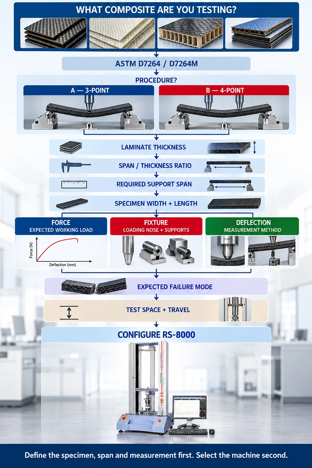
A useful configuration needs to be built around the coupon:
expected working force
Procedure A or Procedure B
specimen thickness
required support span
specimen width and length
loading/support geometry
required deflection measurement
available test space and travel
required output and reporting
For many CFRP and GFRP coupon tests, the key selection issue is unlikely to be whether a 50 kN frame can physically survive the load.
The more useful question is whether the complete system measures the actual working range appropriately and reproduces the required geometry.
That is the difference between selecting a UTM and configuring a test system.
One Coupon, One Configuration Example
Take the earlier specimen:
Material: CFRP laminate
Procedure: ASTM D7264 Procedure A
Thickness: 4.00 mm
Width: 13.0 mm
Required ratio: 32:1
Support span: 128 mm
Expected peak force: approximately 1–2 kN
Required results: flexural strength + force-deflection curve
From this information alone, several equipment requirements are already visible.
The fixture must reach a 128 mm support span.
The machine needs sufficient space for the fixture, coupon and test travel.
The force-measurement configuration should be appropriate for a working load around the expected 1–2 kN region rather than being selected solely from the frame's maximum rating.
If stiffness-related properties are required, the displacement measurement method needs to be defined.
And the loading fixture must correspond to Procedure A.
Only after those conditions are established does:
"Which UTM model?"
become a useful final question.
What to Send With an ASTM D7264 RFQ
"We need an ASTM D7264 machine" tells us the standard, but it does not yet define the test system.
A much more useful RFQ contains:
Standard / revision: ASTM D7264/D7264M-26, or the revision required by your customer
Procedure: A / B / not yet defined
Composite: CFRP / GFRP / other polymer matrix composite
Layup or fiber orientation: if known
Specimen dimensions: thickness × width × length
Expected working load or flexural strength: if available
Required outputs: maximum force / flexural strength / force-deflection / modulus
Deflection measurement requirement: if specified
Test volume: approximate specimens per batch or per day
If the specimen drawing is already available, send it.
For equipment selection, a drawing often answers more useful questions than a requested machine capacity.
FAQ
What is the ASTM D7264 span-to-thickness ratio?
The standard span-to-thickness ratio is 32:1. For example, a 4 mm specimen corresponds to a 128 mm support span under the standard ratio.
What is the difference between ASTM D7264 Procedure A and Procedure B?
Procedure A uses three-point loading with one center loading nose. Procedure B uses four-point loading with two loading noses. In the D7264 four-point arrangement, the loading span is one-half of the support span. Because the stress distributions differ, the two procedures should not be mixed when directly comparing material results.
ASTM D7264 vs ASTM D790: what's the difference?
ASTM D7264 is intended for polymer matrix composite flexural properties, particularly continuous-fiber-reinforced composites. ASTM D790 is primarily a plastics flexural method. D7264 uses a standard 32:1 span-to-thickness ratio compared with the standard 16:1 ratio associated with D790.
Can crosshead displacement be used for composite flexural modulus?
Do not assume crosshead travel and specimen deflection are identical. Crosshead movement can contain machine, fixture, contact and specimen deformation. When a stiffness-related result is required, confirm which displacement measurement the applicable procedure and calculation require.
What size UTM is required for ASTM D7264?
There is no single kN capacity for every D7264 application. Start with specimen dimensions, expected working load, support span and required measurement outputs. Then select the frame, load measurement range, bending fixture and deflection measurement as one system.
The Number Is Only Useful If the Test Behind It Is Defined
ASTM D7264 is easy to recognize on a laboratory floor.
Two supports. One or two loading noses. A composite coupon bending between them.
What separates a useful material property from just another peak-force reading happens in the details.
Was Procedure A or B used?
Was the span based on the actual coupon thickness?
Was the specimen cut in the intended material direction?
Where did it fail?
Was the damage flexural, interlaminar or contact driven?
Where did the reported deflection come from?
And was the force-measurement system configured around the load the coupon actually produced?
Those questions should be answered before choosing the largest kN number in a UTM catalog.
For an ASTM D7264 project, start with the specimen drawing and test requirement. From there, the support span, fixture geometry, force range, displacement measurement and machine configuration become much easier to define.
Define the specimen, span and measurement first. Select the machine second.
