
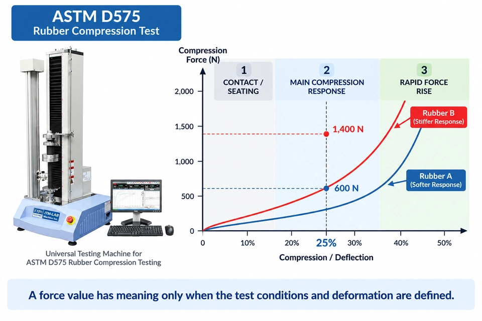
A rubber specimen reaches 25% compression at 600 N. Another requires 1.4 kN to reach the same deflection.
Which rubber is better?
The higher number does not answer that question by itself.
For a seal, a relatively compliant compound may be needed to conform to mating surfaces. A rubber support or vibration-control component may need a much stiffer response to limit movement under load. What matters is whether the material delivers the right compression behavior for the application.
That is the problem ASTM D575 is designed to investigate.
ASTM D575-91(2024), Standard Test Methods for Rubber Properties in Compression, provides two procedures for determining the compression-deflection characteristics of rubber compounds. Rather than treating compression as simply a "maximum force before failure" test, it examines the relationship between force and deformation.
For a test engineer, however, knowing the standard number is only the beginning. Specimen geometry, platen alignment, test rate, force range, and even the way displacement is measured can influence the result.
This guide looks at those details—and at how they affect the configuration of a universal testing machine for rubber compression testing.
What ASTM D575 Actually Tells You
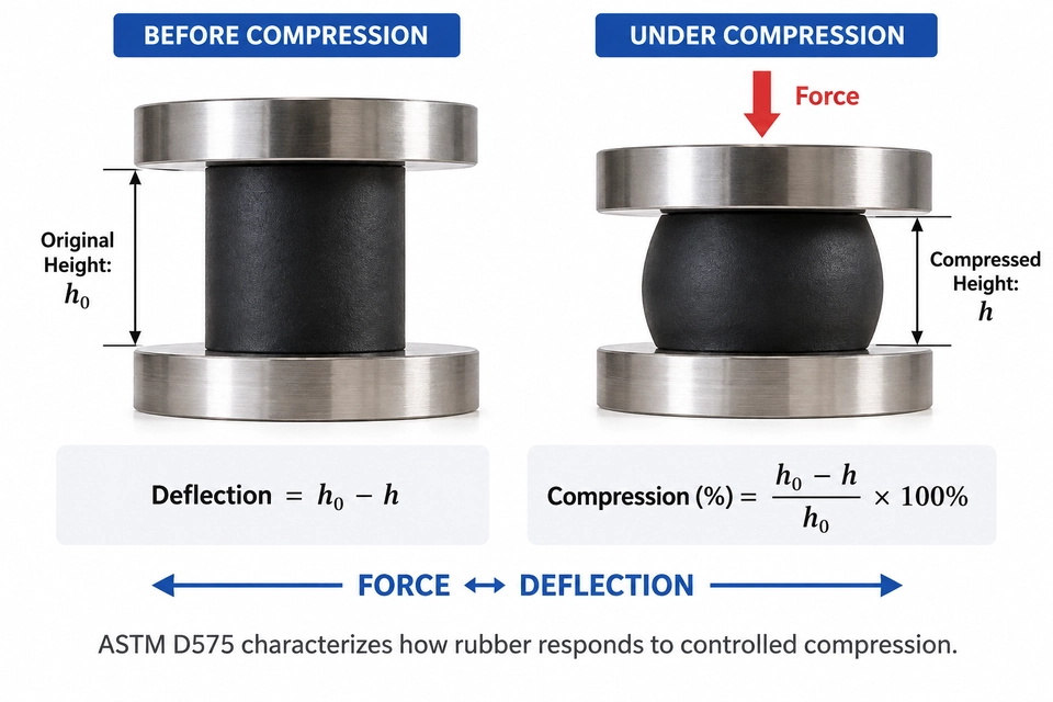
ASTM D575 is primarily a comparative test for the stiffness of rubber materials in compression.
Its basic engineering relationship is straightforward:
Force ↔ Deflection
One way to use that relationship is to compress a specimen by a defined amount and measure the force required. Another is to apply defined forces and measure how much the specimen deflects.
That makes ASTM D575 useful when comparing rubber compounds intended for compressive applications such as sealing materials, elastomeric pads, mounts, and other components where deformation under load matters.
It is important to understand what the standard does not tell you.
A larger force value is not automatically a better result, and ASTM D575 is not simply a test of how much compression a specimen can survive before catastrophic failure.
It is a way of characterizing the material's compression response under controlled conditions.
The standard covers rubber compounds other than materials normally classified as hard rubber or sponge rubber. If you are evaluating a finished gasket, molded component, foam, or cellular rubber product, first check whether ASTM D575 is the appropriate method or whether a product-specific specification applies.
ASTM D575 Method A vs Method B
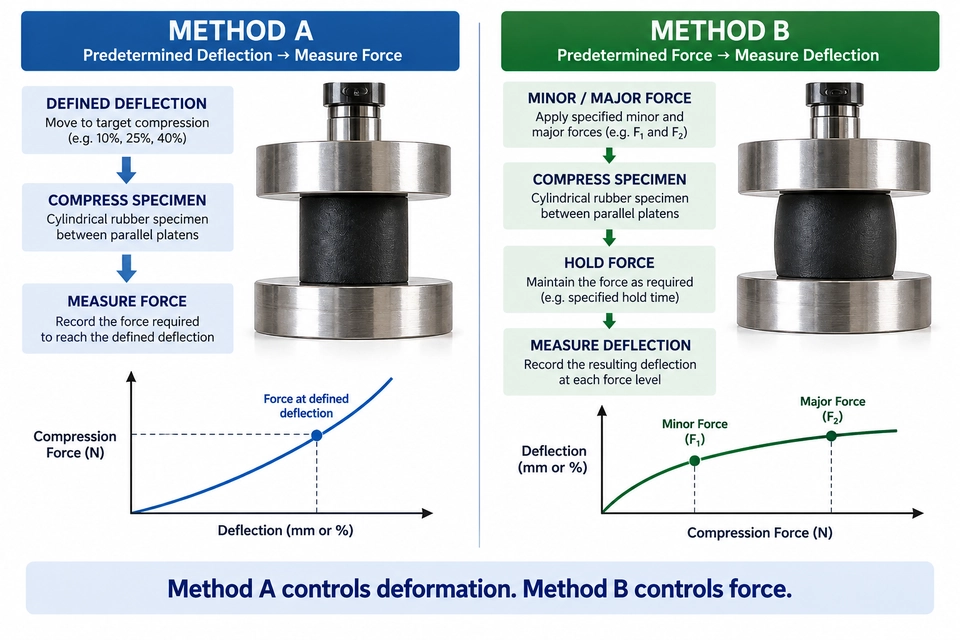
ASTM D575 contains two procedures. They investigate the same general material behavior from different directions.
The easiest way to understand the difference is to ask:
What is controlled during the test?
Method A: Set the Deflection, Measure the Force
In Method A, a predetermined deflection is applied to the cylindrical rubber specimen and the corresponding force is recorded.
Suppose the requirement calls for the response at a defined compression. The testing machine moves the compression platen until that deformation is reached, and the force required to reach it becomes the important measurement.
The practical question is:
How much force does this rubber require to reach the specified deflection?
If two specimens have equivalent geometry and are tested under the same conditions, the one requiring greater force at that deflection has the stiffer compression response.
Method B: Apply Defined Forces, Measure the Deflection
Method B reverses the logic.
Predetermined minor and major forces are applied, and the resulting deflection is measured.
The practical question becomes:
How far does this rubber deform under the specified compressive load?
This distinction matters when configuring the test system. Method B is not simply a matter of driving the crosshead until a force value briefly appears on the screen. The force must be controlled as required by the procedure while the deflection is determined.
For a viscoelastic material such as rubber, maintaining a force is a meaningful part of the test. The specimen can continue responding while the load is held.
A machine that can reach the required force is therefore not automatically configured well for a force-controlled rubber test. Control stability matters too.
| Test Parameter | Method A | Method B |
|---|---|---|
| Controlled variable | Deflection | Predetermined forces |
| Measured response | Force | Deflection |
| Engineering question | How much force is needed for this deformation? | How much deformation occurs under this load? |
| Machine consideration | Displacement and force measurement | Force control, hold stability, and deflection measurement |
Use the method required by the applicable specification. Do not select Method A or Method B simply because one is easier to program.
How to Read a Rubber Compression Force-Deflection Curve
A single force value is useful, but the complete curve tells a better story.
Plot compression force on the vertical axis and deflection—or percentage compression—on the horizontal axis.
Now imagine two equivalent specimens.
At 25% compression:
Rubber A = 600 N
Rubber B = 1,400 N
Rubber B shows a stiffer compression response at that point.
That conclusion is valid only if the comparison is genuinely like-for-like. Specimen geometry, conditioning, test rate, and other relevant conditions must be comparable.
The shape of the curve also deserves attention.
Near the beginning of a compression test, the system is establishing contact and seating the specimen between the platens. After stable contact, the curve reflects the main compression response of the specimen. At greater deformation, force may rise much more rapidly.
This is one reason a compression curve should not be treated as though every millimeter of crosshead movement represents identical material behavior.
Rubber Does Not Simply Get Shorter
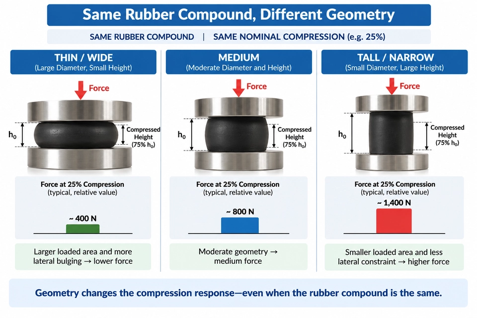
Put a rubber cylinder between two platens and push down. Its height decreases—but the material also wants to move outward.
The specimen bulges laterally.
That means the measured compression response is affected not only by the rubber compound, but also by specimen geometry and the way its surfaces are constrained.
A thin, wide specimen does not necessarily behave like a tall, narrow specimen made from exactly the same compound.
This is why it is dangerous to treat a compression force such as "1.2 kN" as an independent material property.
Change the diameter or thickness and you may change the force required to reach the same nominal percentage compression.
In elastomer engineering, this behavior is often discussed in terms of geometry or shape factor: broadly, the relationship between the loaded area and the area available for the rubber to bulge.
The practical lesson is more important than the terminology:
Same rubber compound + different specimen geometry can produce a different compression response.
That has two practical consequences.
First, specimen geometry must remain consistent when materials or production batches are compared.
Second, the compression platen should be sized for what happens during loading, not just for the specimen dimensions before the test begins.
A platen that barely covers the original specimen can become a poor choice once the rubber starts to bulge.
Where Does Compression Actually Start?
This sounds like a simple question until you test a very soft rubber.
When does the specimen height become the reference height?
Is it when the upper platen appears to touch the specimen? When the load cell first detects force? Or after a defined seating condition has been established?
If the zero point is set before full contact, the apparent specimen height can be too large. If an excessive preload is applied first, a soft specimen may already be compressed before the test is considered to have started.
That error then follows every percentage-deflection calculation based on the initial height.
Consider a specimen with an original height of 12 mm.
A nominal 25% compression corresponds to:
12 mm × 25% = 3 mm
If the reference height is established incorrectly, the commanded 3 mm movement no longer represents the intended percentage of the actual specimen height.
The correct contact, seating, and reference procedure should therefore come from the applicable test method rather than from an arbitrary operator preference.
For routine QC, consistency between operators and specimens is just as important.
Why Test Speed Can Change the Result
Rubber is viscoelastic.
Its response depends not only on how far it is deformed, but also on how quickly that deformation occurs.
Compress the same specimen rapidly and the polymer structure has less time to respond. Compress it more slowly and relaxation can occur during loading.
The measured force can therefore change with test rate.
This matters when a laboratory compares compounds, suppliers, or production batches. A force difference is not necessarily a material difference if the specimens were tested at different rates.
The useful rule is simple:
Never compare rubber compression values without also checking the specimen geometry and test conditions.
The test rate used for compliance work should follow the applicable ASTM D575 procedure and any governing customer or product specification.
Rubber Hardness and Compression Stiffness Are Not the Same Property
Another common mistake is assuming that a Shore hardness value predicts the ASTM D575 result.
It does not do so directly.
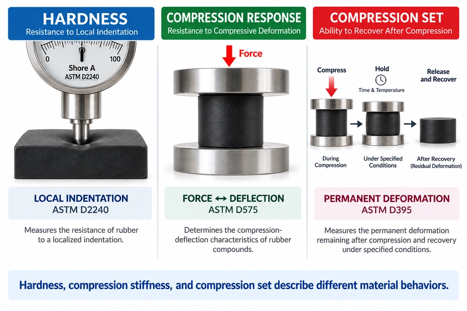
A durometer hardness test such as ASTM D2240 measures a localized indentation response. ASTM D575 examines the compression-deflection behavior of an entire specimen.
The latter is influenced by specimen geometry, loaded area, lateral deformation, and the defined compression condition.
Two rubber compounds with similar hardness values should therefore not automatically be expected to produce identical force-deflection curves.
That distinction becomes particularly important when a drawing specifies one property while the actual component design depends on another.
A seal may need a specified hardness for material control but still require separate compression behavior to ensure the correct sealing load.
ASTM D575 vs ASTM D395: Compression Response Is Not Compression Set
These tests answer different engineering questions.
ASTM D575 asks:
How strongly does the rubber resist deformation while it is being compressed?
Compression-set testing asks:
How much permanent deformation remains after a defined compression exposure and recovery?
Consider a seal.
Its compression stiffness influences the force generated when the seal is installed.
Its compression set helps describe its ability to recover after being held in a compressed state.
Both can matter to performance, but one cannot substitute for the other.
| Engineering Question | Property |
|---|---|
| How does the surface resist indentation? | Rubber hardness |
| How strongly does the specimen resist compression? | Compression-deflection behavior |
| How much permanent deformation remains after compression and recovery? | Compression set |
These are related aspects of rubber behavior, not interchangeable measurements.
How to Perform an ASTM D575 Rubber Compression Test
A compliant laboratory procedure should always be built from the applicable edition of ASTM D575 and any additional product or customer requirements.
From an equipment perspective, the work begins before the specimen enters the testing machine.
Start by confirming whether Method A or Method B applies and identifying the specimen geometry. The expected force range, required deformation, and measurement method should also be known—or at least estimated—before the load cell and fixtures are selected.
Measure the specimen as required and establish the correct initial reference condition.
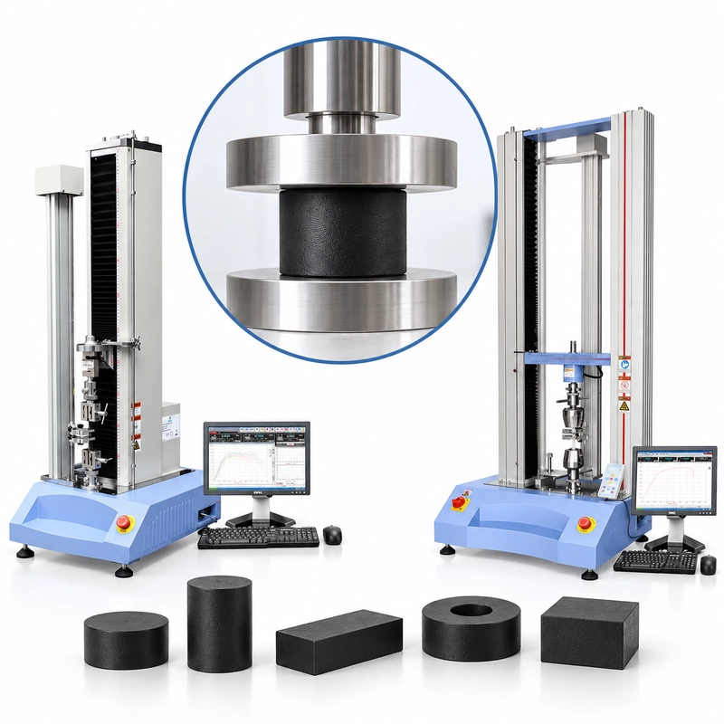
Next, install compression platens appropriate for the specimen and expected load. The specimen should sit correctly relative to the loading axis, and the system should provide sufficient platen area for lateral expansion during compression.
For Method A, the machine applies the specified deflection and records force.
For Method B, the specified force sequence is applied and deflection is determined under the required force-controlled condition.
The useful output is rarely just "maximum force." Depending on the requirement, the report may include force at a specified deflection, deflection at specified force, individual specimen results, averages, and the complete force-deflection curve.
When results are used for comparison, specimen geometry and test conditions need to remain consistent.
Platen Parallelism: A Small Setup Error That Can Distort the Curve
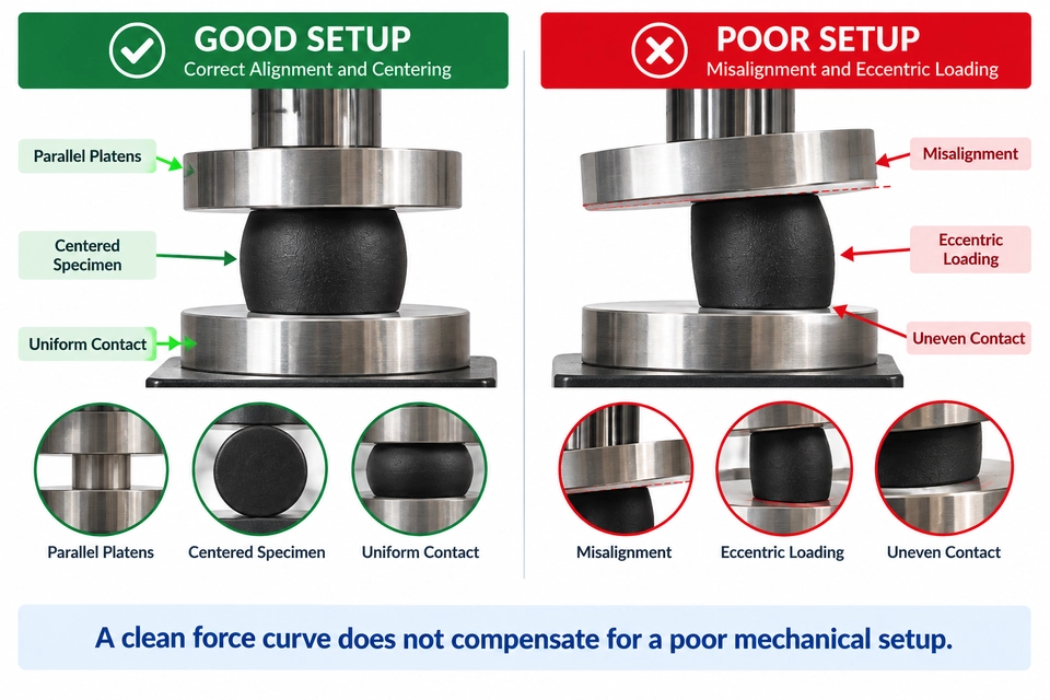
Imagine the upper platen approaching the rubber at a slight angle.
One side contacts first.
The specimen begins deforming locally before the opposite side is fully engaged.
The machine may still produce a smooth-looking force curve, but the specimen is no longer experiencing the intended uniform axial compression.
Possible consequences include uneven bulging, eccentric loading, and poor repeatability between specimens.
The same problem occurs when the specimen is positioned noticeably off the loading axis.
For this reason, a rubber compression setup should be evaluated as a complete mechanical chain:
Load Cell → Fixture → Upper Platen → Specimen → Lower Platen
not simply as a testing machine with enough force capacity.
Where tighter parallelism is required, an appropriate self-aligning arrangement can also be considered as part of the fixture design.
Crosshead Travel Is Not Always the Same as Specimen Deflection
This distinction matters when displacement accuracy becomes important.
The testing machine knows how far its crosshead has moved. That does not necessarily mean the rubber specimen has deformed by exactly the same amount.
Measured crosshead movement can include compliance elsewhere in the test system.
Conceptually:
Crosshead Movement = Specimen Deformation + System Compliance
Take a purely illustrative example.
Suppose the machine reports:
3.00 mm crosshead movement
while the machine and fixture system contribute:
0.12 mm of displacement under load
It would be incorrect to assume automatically that the rubber itself compressed by exactly 3.00 mm.
Those numbers are only an example; actual compliance depends on the machine, fixture, and applied force.
For routine ASTM D575 work, crosshead displacement can be suitable when used in accordance with the required procedure. Where more accurate specimen-deflection measurement is required, direct displacement measurement closer to the compression platens can reduce the influence of machine compliance.
This becomes increasingly relevant when the target deformation is small relative to the compliance of the complete test system.
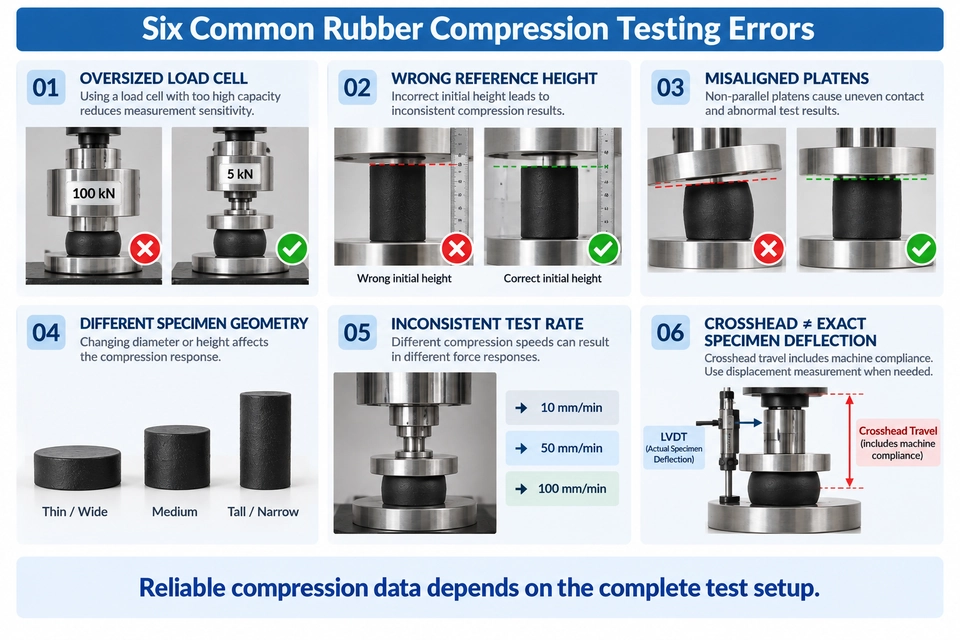
Six Common ASTM D575 Testing Errors
Some problems are obvious. Others can produce perfectly believable numbers while still reducing the quality of the test.
1. Oversizing the Force Measurement Range
A specimen expected to peak at a few hundred newtons should not automatically be paired with the largest available load cell simply because the frame can accept it.
Choose the force measurement range around the actual test.
2. Starting From the Wrong Reference Height
Poor contact detection or excessive seating force can change the effective starting point for percentage compression.
3. Ignoring Platen Alignment
Angular contact changes the way the specimen begins to deform and can reduce repeatability.
4. Comparing Different Specimen Geometries as Though They Were Equivalent
Rubber geometry affects lateral deformation and the measured compression response.
5. Changing the Test Rate Between Samples
Because rubber is viscoelastic, rate differences can appear as material differences.
6. Assuming Crosshead Displacement Equals Exact Specimen Deformation
At higher loads or tighter displacement tolerances, system compliance may become significant.
What Capacity Universal Testing Machine Do You Actually Need?
"ASTM D575 testing machine" is not enough information to choose a machine capacity.
The standard describes the test method. It does not tell you whether your particular specimen needs 300 N, 3 kN, or 18 kN.
Consider three hypothetical applications.
Application A — Expected Peak Force: 300 N
A laboratory is testing relatively soft, small rubber specimens. Selecting a very high-capacity force measurement system simply because "bigger is safer" may be counterproductive.
Application B — Expected Peak Force: 3 kN
The requirement remains within a relatively low-force compression range, but the machine, load cell, and platens must all support the complete test with suitable capacity.
Application C — Expected Peak Force: 18 kN
A 5 kN frame cannot perform the test simply because it is capable of ASTM D575-style compression testing in principle. A higher-capacity system is required.
The engineering principle is:
Capacity needs adequate headroom, but more capacity does not automatically mean better measurement.
If the expected force is unknown, specimen material, geometry, and required compression provide a much better starting point than the ASTM number alone.
Choosing the Load Cell for Rubber Compression Testing
Machine capacity and load cell capacity are related, but they are not the same decision.
Suppose a frame is capable of 5 kN.
That does not mean every specimen should automatically be tested with the same 5 kN force range.
The expected working force should be considered when selecting the load cell so that the measurement system is appropriate for the forces that will actually occur.
A better selection sequence is:
Expected Specimen Force → Load Cell Range → Frame Capacity
If the laboratory needs to test both very soft elastomers and substantially stiffer specimens, multiple force ranges may be worth considering rather than compromising all tests around one oversized configuration.
Compression Platens Need More Than the Right Diameter
Platen selection usually starts with specimen dimensions, but it should not stop there.
The fixture needs to accommodate the loaded specimen, lateral bulging, expected maximum force, available test space, and required alignment.
For rubber, the loaded geometry can matter more than the unloaded photograph.
If a specimen starts at 29 mm diameter, choosing a platen simply because it is fractionally larger than 29 mm misses the point.
The specimen may spread considerably as compression increases.
Leave practical margin for the actual deformation.
RS-8010A or RS-8000 for ASTM D575 Testing?
Once the expected force range is known, machine selection becomes much easier.
For lower-force rubber compression applications, the ITM-LAB RS-8010A can be configured from 50 N to 5 kN.
For higher-force requirements, the RS-8000 covers configurations from 10 kN to 50 kN.
Neither model should be selected solely because the purchase request says "ASTM D575."
| Selection Factor | RS-8010A | RS-8000 |
|---|---|---|
| Force range | 50 N–5 kN | 10–50 kN |
| Lower-force rubber specimens | Primary application range | Usually unnecessary |
| Higher-force specimens | Limited by configuration | Better suited |
| Compression platens | Configurable | Configurable |
| Force-deflection recording | Yes | Yes |
| Final configuration | Based on specimen and test | Based on specimen and test |
The machine should fit the working test range, not merely have a capacity greater than the expected peak.
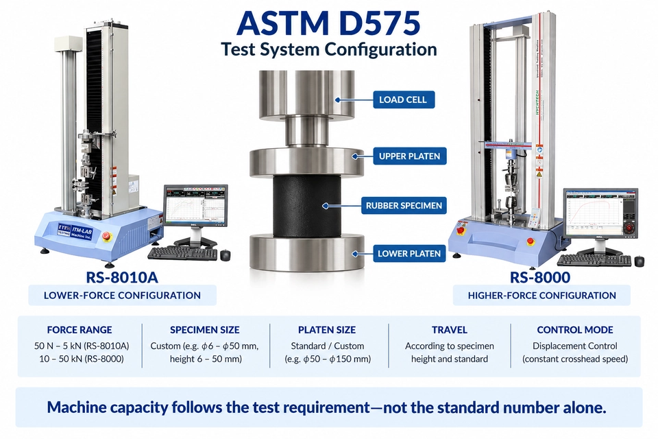
Worked Example: Configuring a Rubber Compression Test
Consider a customer testing a rubber gasket compound.
The specimen is approximately:
29 mm diameter × 12.5 mm thick
The target is:
25% compression
and the estimated peak force is:
about 800 N
These values are an equipment-selection example, not ASTM D575 requirements.
The target specimen deformation is:
12.5 mm × 25% = 3.125 mm
So the system needs to control and measure roughly 3.1 mm of compression under the defined test condition.
The estimated force is below 1 kN. That points toward a lower-force UTM configuration rather than automatically moving to a 50 kN system.
Next comes the fixture.
The platen should comfortably accommodate the specimen while allowing for lateral bulging. Its capacity must exceed the expected test force, and alignment needs to support repeatable compression.
For this example, an RS-8010A configured with an appropriately ranged load cell and suitable compression platens would be a logical starting point.
Change one variable, however, and the answer may change.
If the specimen becomes much larger, the compound substantially stiffer, or the required compression pushes the expected force beyond the selected system range, the machine configuration needs to be reconsidered.
That is why specimen data should come before the quotation.
What We Need to Configure Your ASTM D575 Test System
A request that says only:
"Please quote an ASTM D575 testing machine."
still leaves most of the important engineering questions unanswered.
For a useful quotation, send as much of the following information as you have:
| Information | What to Send |
|---|---|
| Material | EPDM / NBR / silicone / other |
| Specimen geometry | Diameter × thickness, or drawing |
| ASTM D575 method | Method A / Method B / not sure |
| Target compression | % or mm |
| Expected maximum force | N or kN, if known |
| Test speed | If specified |
| Test volume | Tests per day |
| Other requirements | Customer specification / internal method |
| Sample information | Photo or drawing |
Don't Know the Expected Force?
That is common during the equipment-selection stage.
Send the material, specimen dimensions, target compression, and test requirement first. These provide a practical basis for defining the load cell, platen, and machine configuration.
FAQ
What is ASTM D575 used for?
ASTM D575 is used to determine and compare the compression-deflection characteristics of rubber compounds. It is particularly useful when compression stiffness matters to the intended material application.
What is the current version of ASTM D575?
The current ASTM listing is ASTM D575-91(2024), Standard Test Methods for Rubber Properties in Compression. Always confirm the edition required by your customer, laboratory, or contract before testing.
What is the difference between ASTM D575 Method A and Method B?
Method A applies a predetermined deflection and records the resulting force.
Method B applies predetermined minor and major forces and measures deflection. Its force-controlled portion also makes stable force holding an important test-system consideration.
Is ASTM D575 a compression strength test?
Not in the usual sense of loading a specimen until catastrophic compressive failure.
ASTM D575 is primarily concerned with compression-deflection behavior and comparative stiffness.
Is rubber hardness the same as compression stiffness?
No. Hardness testing measures a localized indentation response. Compression stiffness describes the response of the specimen under compressive deformation and is also influenced by specimen geometry and test conditions.
Is ASTM D575 the same as ASTM D395 compression set?
No. ASTM D575 examines compression-deflection behavior during loading. ASTM D395 addresses permanent deformation after a rubber specimen has been compressed under defined conditions and allowed to recover.
Can I use crosshead displacement for ASTM D575?
Crosshead displacement can be suitable for ASTM D575 testing. For applications requiring more accurate specimen-deflection measurement, direct displacement measurement closer to the platens can help reduce the influence of machine and fixture compliance.
What load cell should I use for ASTM D575?
Choose the load cell according to the expected working force of the specimen rather than selecting one solely from the machine's maximum capacity.
If the expected force is unknown, start with the rubber type, specimen dimensions, and target compression.
Can a 5 kN universal testing machine perform ASTM D575?
Yes, provided the expected force, fixture requirements, and measurement range fit within the configured system.
Some ASTM D575 applications require far less than 5 kN, while others may exceed that capacity.
What size compression platen do I need?
The platen should accommodate the specimen throughout the required compression, not only its original diameter or width. Rubber can bulge laterally as it is compressed, so the loaded geometry should be considered when selecting platen size.
Configure Your Rubber Compression Test Around the Specimen
There is no single "ASTM D575 machine" that is right for every rubber compound.
A small, compliant specimen generating a few hundred newtons and a larger, stiffer specimen generating tens of kilonewtons may follow the same test standard but require very different force ranges, platens, and machine frames.
Start with the test.
What material are you testing?
What are the specimen dimensions?
How far must it be compressed?
Method A or Method B?
What force do you expect, if known?
From there, the load cell, compression platens, displacement measurement, and UTM capacity can be configured around the actual requirement.
For lower-force applications, ITM-LAB offers the RS-8010A, 50 N–5 kN.
For higher-force requirements, the RS-8000, 10–50 kN provides additional capacity.
