
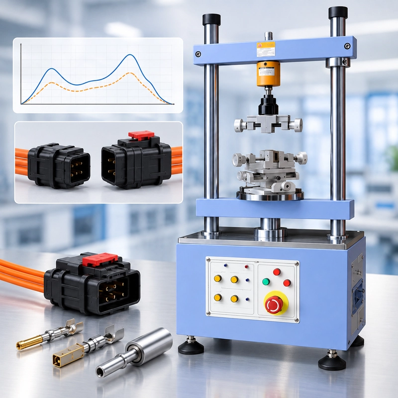
Connector insertion and withdrawal force looks like a straightforward mechanical measurement: hold one connector, move the mating half into it, record the force, and reverse the motion.
In practice, the measurement is more sensitive to the test setup than it first appears.
A load cell cannot distinguish contact resistance from housing interference, seal compression, latch engagement, or force introduced by misalignment. It simply measures the axial load transmitted into the sensor. Whether that number represents the force you intended to measure depends on how the specimen, fixture, motion, and measurement boundary were defined.
This distinction is central to IEC 60512-13-2 Test 13b.
IEC 60512-13-2 specifies a method for measuring the insertion and withdrawal forces of mating connectors, contacts, or specified test gauges. Unlike a complete engaging/separating force measurement, Test 13b is intended to determine insertion and withdrawal force without the influence of locking, latching, sealing, engaging, separating, or similar mechanisms.
For engineers setting up this test, the first question should therefore not be:
“What size load cell do we need?”
It should be:
“What force are we actually trying to isolate?”
Where Test 13b Fits in Connector Mechanical Testing
IEC 60512 contains a family of test and measurement methods for connectors used in electrical and electronic equipment. IEC 60512-13-2 covers mechanical operation Test 13b: insertion and withdrawal forces.
It should not be confused with every test in which a connector is pushed, pulled, mated, or separated.
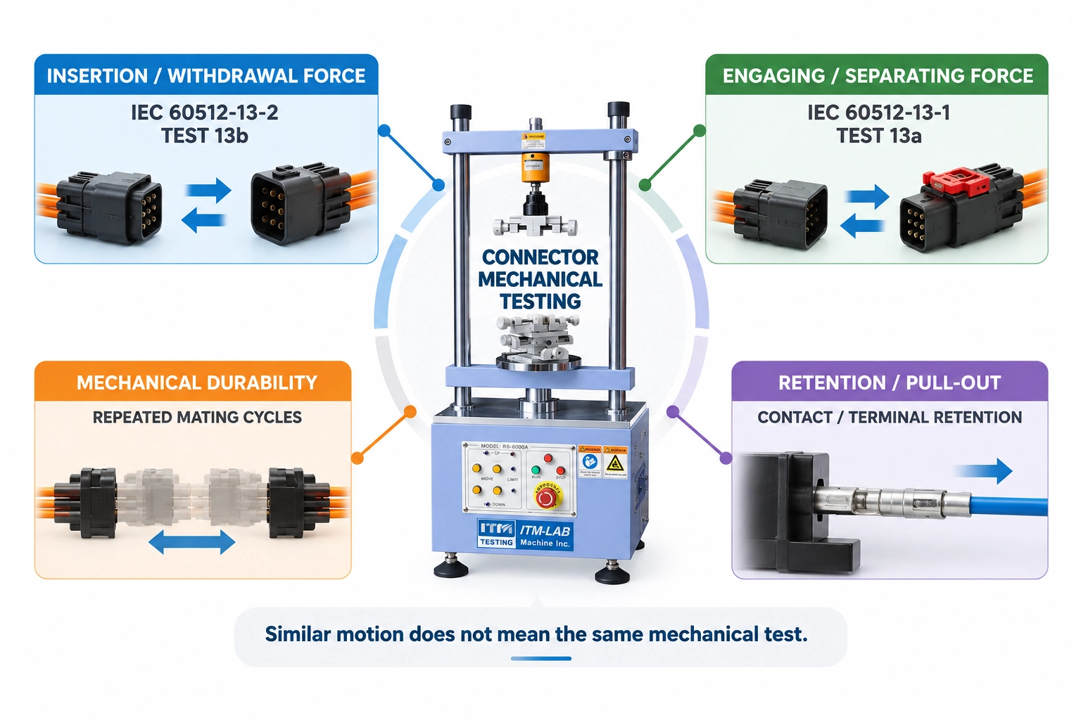
A connector manufacturer may need to evaluate mating-interface force, complete engaging/separating force, repeated mating durability, contact retention, or terminal pull-out. These tests answer different engineering questions even when similar force-measurement equipment is used.
The distinction between Test 13a and Test 13b is particularly important.
IEC 60512-13-1 Test 13a addresses the force required to fully engage or separate mating connectors, including the effect of locking, latching, sealing, engaging, separating, and similar mechanisms.
IEC 60512-13-2 Test 13b, by contrast, measures insertion and withdrawal forces without those mechanisms influencing the intended measurement.
That difference can be substantial on a sealed automotive connector with a latch or secondary locking feature. The force an operator feels while closing the complete connector is not necessarily the same quantity that Test 13b is intended to measure.
Start by Defining the Measurement Boundary
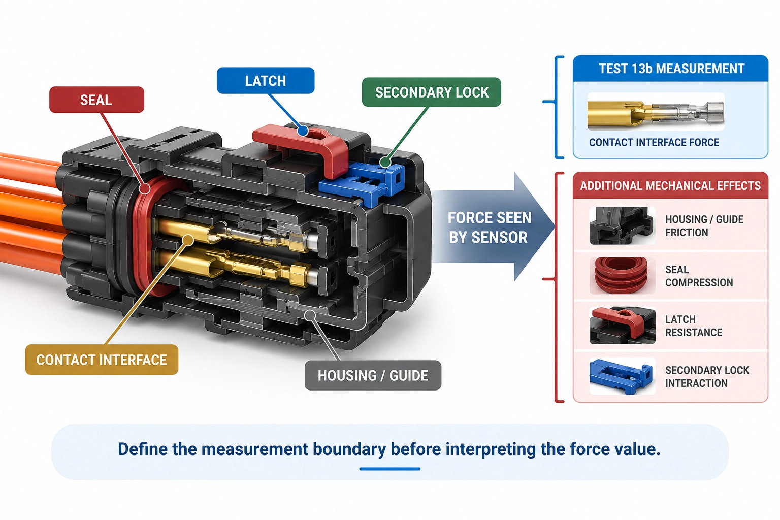
Consider a sealed multi-position connector. During mating, the load transmitted through the test machine may contain several mechanical contributions:
Contact interaction + housing guidance + seal compression + latch resistance + secondary locking features + unintended side load
The force sensor sees the combined reaction. It does not identify where each part of that force originated.
This is why the measurement boundary needs to be established before the test is configured.
For Test 13b, locking, latching, sealing, and similar mechanisms should not simply enter the result because they happen to be present on the finished connector. The applicable product or detail specification needs to be reviewed, and the specimen or test arrangement configured accordingly.
This also explains why a Test 13b result should not automatically be compared with the force required by a person or an assembly machine to operate the complete production connector. Those two measurements may represent different mechanical quantities.
Suppose a finished connector produces a 60 N peak during mating. That does not automatically mean its Test 13b insertion force is 60 N. If part of the peak comes from seal compression or latch engagement, the complete mating-force peak and the Test 13b insertion force are not equivalent.
The standard number alone does not resolve this distinction. The test setup does.
Test 13b Is Not Limited to a Complete Connector Pair
A useful feature of IEC 60512-13-2 is that the test concept is broader than simply mating one finished connector assembly with another.
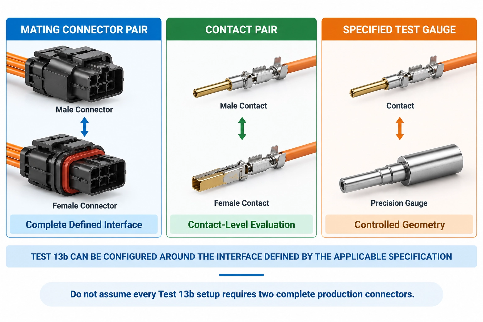
Depending on the applicable specification and the purpose of the evaluation, the test may involve mating connectors, a pair of individual contacts, or specified insertion and withdrawal gauges.
With a complete mating connector pair, the test evaluates the defined insertion/withdrawal behavior of the connector interface while the surrounding geometry is controlled according to the test requirement.
At the individual contact level, engineers can evaluate the mating behavior of the contact interface without automatically including every mechanical contribution from the complete connector housing, where the applicable requirement permits such a setup.
A specified test gauge provides another option. Gauge-based testing is useful when a controlled mating geometry is required rather than another production component whose dimensions also contain manufacturing variation.
This creates an important engineering distinction.
Testing:
Production Connector A ↔ Production Connector B
introduces dimensional variation from both components.
Testing:
Production Contact ↔ Defined Gauge
can provide a controlled mating geometry.
That distinction can be useful during connector development, tolerance studies, supplier comparison, and incoming quality evaluation.
Alignment Is More Subtle Than Keeping the Connector Straight
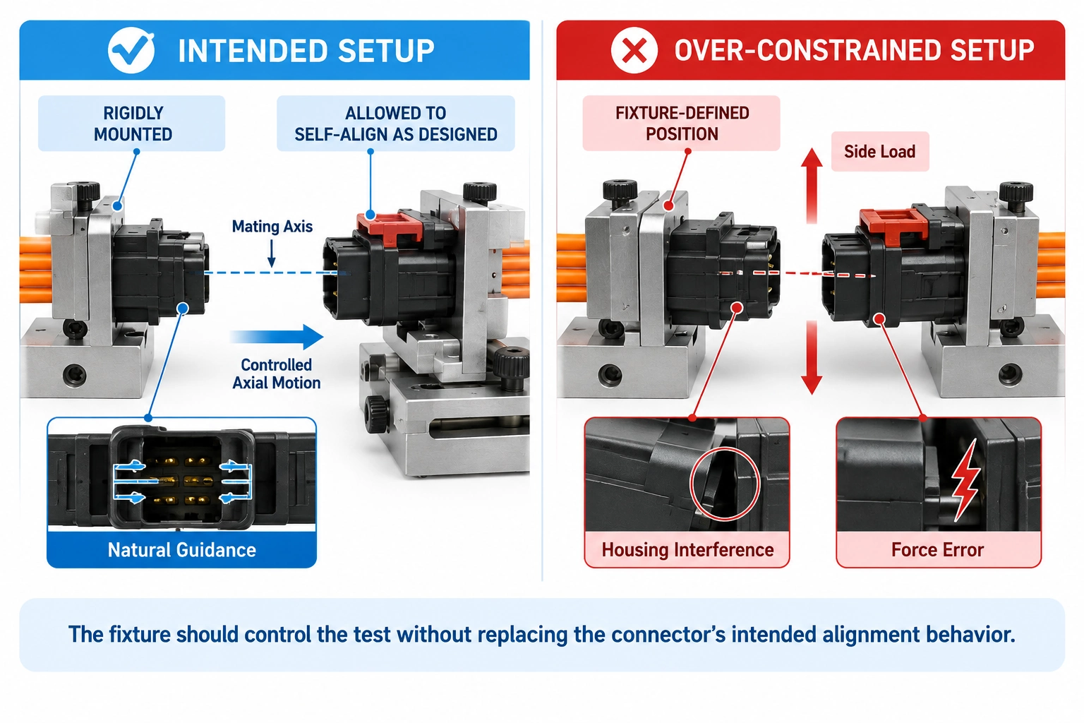
Misalignment is an obvious source of error. If the mating axes are offset or angularly displaced, part of the measured force may come from housing interference or side loading rather than the intended insertion behavior.
The less obvious mistake is trying to eliminate that problem by rigidly constraining everything.
Under the Test 13b mounting approach, one component is rigidly mounted while the mating component is allowed to use the self-alignment provided by the connector design.
That matters because a production connector may use lead-ins, guide features, compliant geometry, or other features to establish its final mating position. If a laboratory fixture clamps both halves so rigidly that the connector can no longer use its intended alignment behavior, the fixture begins to define the mating geometry.
The result can be highly repeatable and still be wrong for the intended measurement.
This distinction is worth emphasizing:
Fixture repeatability is not the same as measurement validity.
A good fixture establishes a repeatable datum and controls the intended test axis without unnecessarily changing how the mating components locate relative to one another.
Too little control creates a different problem: uncontrolled tilting or lateral movement. Fixture design therefore needs to reproduce the intended mechanical boundary, not simply maximize rigidity.
Test Speed: 50 mm/min Is a Limit, Not a Universal Setpoint
Unless otherwise specified by the applicable detail specification, IEC 60512-13-2 calls for insertion and withdrawal at a constant speed not exceeding 50 mm/min.
The wording matters.
It does not mean every Test 13b should automatically be programmed at exactly 50 mm/min.
If the applicable product or detail specification defines another required test condition, that requirement needs to be followed.
This becomes important when comparing results from different laboratories or suppliers. A report containing only:
Insertion Force: 28 N
does not provide enough information to reproduce the measurement.
The specimen configuration, fixture arrangement, motion condition, and other relevant test parameters also need to be known.
From an equipment perspective, maximum machine speed is therefore not the important specification. The more relevant question is whether the system can maintain the required controlled low-speed motion smoothly and repeatably over the actual connector travel.
Lubrication and Surface Condition Can Change the Result
Connector insertion and withdrawal force is strongly influenced by friction, which makes lubrication easy to underestimate.
Where the applicable detail specification requires a specified lubricant, it needs to be applied as required. A dry connector and a lubricated connector should not be treated as equivalent specimens simply because they share the same part number.
Previous use also matters.
Contact surfaces can change after mating. Lubricant can redistribute, contact surfaces can burnish, small molded interference features can settle or wear, and the mechanical relationship between the mating parts can change.
A connector that has never been mated may therefore produce a different force response from the same connector after several operations.
That difference is not automatically evidence of a failed product.
It may simply mean that the interface condition has changed.
The important point is to define which specimen condition is being evaluated and keep it consistent when results are compared.
Why the First and Last Operations Matter
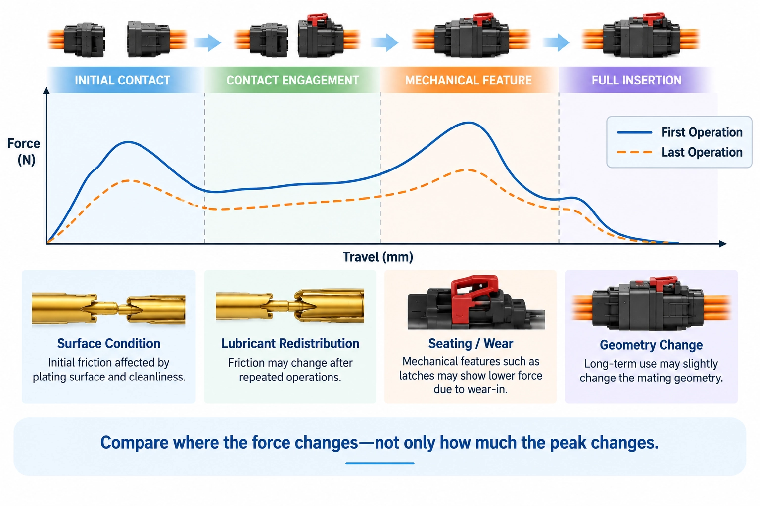
IEC 60512-13-2 requires the specified number of complete insertion and withdrawal operations to be performed, with force measurements recorded at least on the first and last operations.
That provides more information than a single peak-force measurement.
Suppose insertion force is noticeably lower on the final required operation than on the first. Several explanations are possible: the contact surfaces may have seated, lubricant may have redistributed, a small interference feature may have worn, or the connector geometry may have changed slightly during repeated mating.
The difference itself does not identify the cause. It tells the engineer where to investigate.
This is where force-travel data becomes particularly useful.
Instead of comparing only two maximum values, an engineer can examine where along the travel the force changed.
If a peak disappears at the same position where a housing feature initially rubbed against a guide, the likely explanation is different from a uniform reduction in force throughout the contact engagement region.
Six Test Conditions That Deserve Extra Attention
Most unreliable Test 13b results can be traced back to the mechanical boundary conditions around the measurement rather than the numerical capability of the force sensor.
Wrong measurement boundary. A latch, seal, secondary lock, or other mechanism may contribute to a measurement that is supposed to isolate Test 13b insertion/withdrawal force. The result can be repeatable while still representing the wrong quantity.
Over-constrained alignment. Rigidly locating both mating halves can prevent the connector from using its intended self-alignment. Side load or housing interference can then appear as additional insertion resistance.
Fixture-induced deformation. This is especially relevant for molded plastic housings. A clamp that distorts the housing can shift contact cavities or guide surfaces before the crosshead even begins moving.
Incorrect travel. Too little travel can leave the connector incompletely inserted. Too much can drive the assembly into a mechanical stop and produce an artificial end-of-stroke force peak.
Uncontrolled lubrication or specimen history. A new dry specimen, a lubricated specimen, and a connector that has already been mated several times are not necessarily equivalent test conditions.
Incomplete cycle records. Recording one convenient maximum while ignoring the required operations can hide meaningful changes between the initial and final condition.
None of these problems can be corrected later by applying a calibration factor to the force result. They have to be controlled before and during the test.
Troubleshooting Example: An Unexpected Peak Near Full Insertion
Consider a 24-position sealed automotive connector being evaluated for insertion force.
The force-travel curve remains relatively smooth through most of the stroke, but a sharp peak appears shortly before the programmed end position.
It is tempting to conclude:
The insertion force is too high.
That conclusion is premature.
First, locate the peak on the travel axis. Does it occur during contact engagement, or later in the stroke?
Next, compare that position with the connector geometry. Is a seal beginning to compress? Is a latch reaching its engagement feature? Is the housing contacting a guide or mechanical stop? Has the fixture prevented the mating half from making a small self-aligning movement?
Then check the programmed endpoint. If the peak occurs only at the end of travel, determine whether the machine is pushing the connector into a hard stop.
Finally, verify the measurement boundary.
The objective is not to make the peak disappear. The objective is to determine what mechanical event created it.
Only then can the engineer decide whether that event belongs in the Test 13b result.
This is one reason a force-travel record is valuable during connector development. A maximum force tells you how much force was measured. The curve helps explain what happened.
IEC 60512-13-2 vs EIA-364-13
Connector engineers may encounter both IEC 60512-13-2 and EIA-364-13 in customer drawings, qualification plans, and product specifications.
Both involve controlled connector force measurements, and the same general type of servo force-testing platform may support both methods. They should not, however, be treated as interchangeable standard numbers.
IEC 60512-13-2 belongs to the IEC 60512 connector test framework and defines Test 13b insertion and withdrawal forces. EIA-364-13 belongs to the EIA-364 connector test family and needs to be performed according to its own requirements and the applicable product specification.
A laboratory should therefore avoid the shortcut:
“We already perform connector insertion testing, so we will use the same settings.”
A better sequence is:
Standard requirement → product/detail specification → specimen configuration → fixture → motion → measurement → reporting
This keeps an internal laboratory procedure from gradually replacing the actual test requirement.
Typical Products and Industries
IEC 60512-13-2 is not limited to one connector industry. Depending on the applicable product or detail specification, insertion and withdrawal force measurement may be relevant to connectors used in consumer electronics, automotive electronics, industrial equipment, communication hardware, and other electrical and electronic systems.
Typical examples include USB and charging connectors, board-to-board and wire-to-board interfaces, automotive multi-pin and sensor connectors, circular connectors, industrial plugs and sockets, and equipment I/O interfaces.
The important point is not the industry label.
A compact electronics connector and a sealed automotive multi-pin connector may both require insertion and withdrawal force measurement, but their fixture, force range, travel, alignment behavior, and measurement boundary can be completely different.
The standard defines the method. The connector defines much of the test setup.
Translating Test 13b Into a Machine Specification
Once the measurement has been defined, equipment selection becomes much more straightforward.
Start with the expected force rather than the machine's maximum capacity. The load cell should be selected around the working measurement range and required measurement performance, with suitable overload margin. A high-capacity sensor is not automatically the best configuration for a low-force connector simply because it can withstand the load.
Next consider motion. The system needs stable low-speed control for the applicable Test 13b condition, including the default requirement for constant motion not exceeding 50 mm/min unless otherwise specified.
Travel needs to cover the complete defined insertion and withdrawal movement without forcing the specimen into an unintended mechanical stop.
Fixture design should establish the required datum, hold the connector without changing its housing geometry, and preserve the alignment behavior required by the test.
Finally, consider the data requirement. For routine quality checks, the applicable specification may focus on defined force values. For engineering development or failure analysis, synchronized force-travel data can make it much easier to identify where a mechanical event occurs.
A useful machine specification therefore starts with five questions:
What interface is being tested?
What force is expected?
What movement is required?
How should the specimen be held and allowed to align?
What data must be retained?
Only after these questions are answered does the machine model become meaningful.
ITM-LAB Connector Force Test System
For connector force-measurement applications, the ITM-LAB RS-6600A Automatic Insertion and Extraction Force Tester can be configured for insertion, extraction, retention, and related connector mechanical measurements.
For an IEC 60512-13-2 application, the useful configuration is determined by the connector and the applicable test requirement rather than by the machine model alone.
The expected insertion and withdrawal force determines the appropriate force-measurement range. Connector geometry determines the fixture. Mating behavior determines how alignment needs to be handled. The required insertion distance defines usable travel, while the applicable specification determines the motion and test sequence.
Where engineering analysis is required, force and travel data should be treated as part of the measurement system rather than simply as a graph added after the test.
This system-level approach becomes particularly important when one laboratory tests several connector families. A fixture suitable for a rigid industrial circular connector may be inappropriate for a small molded electronics connector even when both fall comfortably within the same load-cell capacity.
What to Provide When Requesting a Test System
“Need a machine for IEC 60512-13-2” is a useful starting point, but it is not enough to configure the measurement system.
Provide the connector model and, where possible, a drawing or clear photographs of the mating interface. Identify the expected insertion and withdrawal force, required travel, applicable speed or detail specification, and whether the connector contains seals, latches, locks, or other mechanisms that affect mating.
It is also useful to state whether the test involves complete connector pairs, individual contacts, or specified gauges; whether force-travel curves are required; and the expected daily test volume.
| Item | Information Needed |
|---|---|
| Test standard | IEC 60512-13-2 + applicable detail/product specification |
| DUT | Connector/contact type and model |
| Drawing | Dimensions and mating geometry |
| Interface | Connector pair / contact pair / gauge |
| Force | Expected insertion and withdrawal range |
| Travel | Required insertion/withdrawal stroke |
| Motion | Required test speed/condition |
| Mechanisms | Seal, latch, lock, secondary lock |
| Specimen | New / conditioned / previously cycled |
| Fixture | Mounting condition and available holding surfaces |
| Data | Force values / force-travel curve / cycle records |
| Throughput | Samples and tests per day |
These inputs usually tell the equipment manufacturer considerably more than the standard number alone.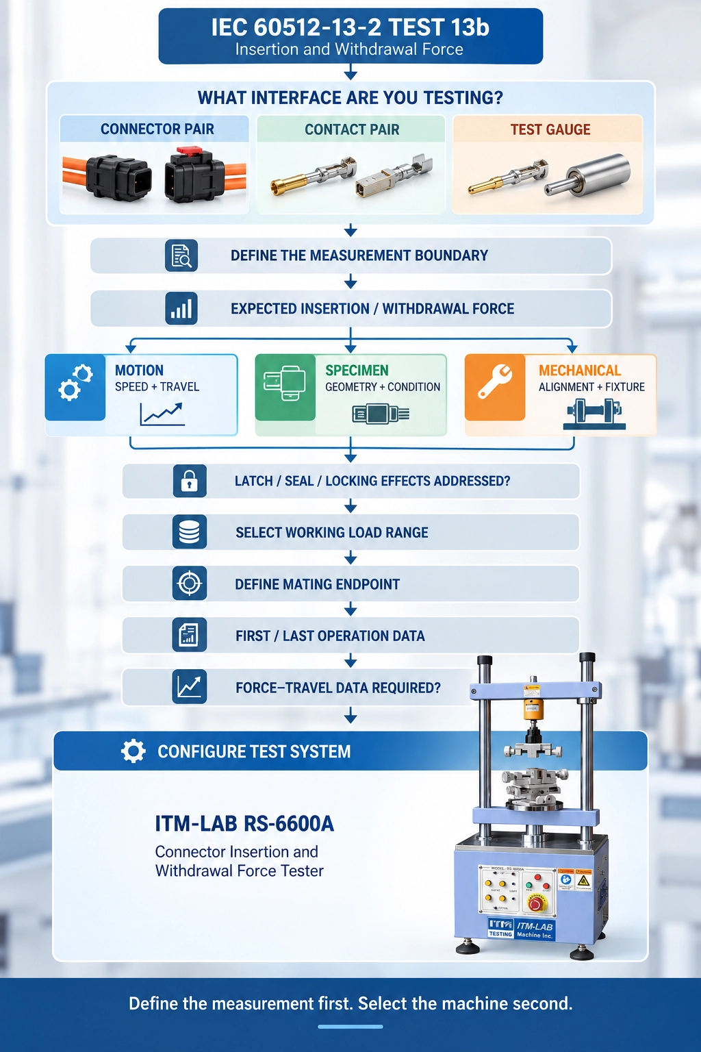
Before You Start the Test
Before collecting data, the engineer should be able to answer several basic questions without relying on assumptions.
Is IEC 60512-13-2 Test 13b actually the specified method? Is the test being performed on a connector pair, contact pair, or gauge? Have locking, latching, sealing, and similar mechanisms been handled correctly for the intended measurement? Does the fixture preserve the required self-alignment? Has specimen condition, including previous mating and lubrication, been defined? Is the programmed travel sufficient for complete insertion without bottoming? Is the working force range appropriate? Are the required first and last operations being recorded?
Finally, identify the document that defines acceptance.
IEC 60512-13-2 provides a test method. It should not be turned into a universal force limit for every connector.
The applicable product or detail specification determines the conditions and performance limits relevant to the particular connector.
Conclusion
IEC 60512-13-2 Test 13b is easy to underestimate because the physical motion is simple. One component moves into another, the direction reverses, and force is measured.
The difficult part is deciding what that force actually represents.
A reliable Test 13b measurement starts by defining the mechanical boundary. From there, the laboratory needs to preserve the connector's intended alignment behavior, control the fixture, specimen condition and lubrication, reproduce the required motion, and distinguish normal mating behavior from bottoming or unrelated mechanical events.
The first and last operations also deserve attention. A change in force does not automatically indicate failure, but it can reveal seating, wear, lubrication changes, interference, or another change in the interface. Looking at where that change occurs along the force-travel curve often provides more useful information than comparing peak values alone.
The same principle applies to test-system selection.
Start with the interface and the measurement—not the machine capacity.
Define what is being tested, what force is expected, how the specimen should align, how far and how fast it needs to move, and what data must be retained. The load cell, fixture, motion system, and software can then be configured around the actual IEC 60512-13-2 requirement.
That is the difference between obtaining a force number and obtaining a connector force measurement that can be reproduced and interpreted.
If You Request an IEC 60512-13-2 Test Solution
Please send the actual connector and test requirements:
Connector / Contact Type: _____
Connector Model: _____
Test Interface: Connector Pair / Contact Pair / Test Gauge
Expected Insertion Force: _____ N
Expected Withdrawal Force: _____ N
Required Travel: _____ mm
Test Speed: _____ mm/min / According to Specification
Latch / Seal / Locking Mechanism: Yes / No
Specimen Condition: New / Conditioned / Previously Mated
Force-Travel Curve Required: Yes / No
Test Cycles / Operations: _____
Test Volume: _____ specimens/day
Drawing / Sample Available: Yes / No
Applicable Specification: IEC 60512-13-2 / Customer Specification / Other: _____
That information allows the test system to be configured around the actual connector:
Load Cell → Fixture → Alignment → Travel → Motion → Data → Test System
For unusual connector geometry, send a drawing or clear photographs of the mating interface together with the test requirement. This makes it possible to evaluate the fixture and measurement configuration before the system is specified.
