
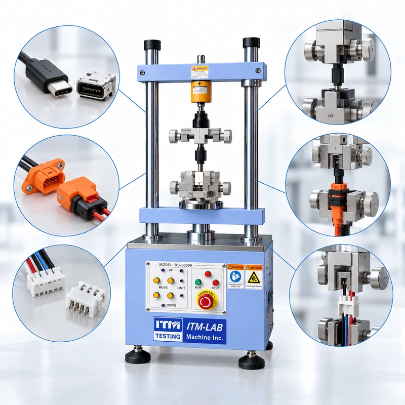
A typical inquiry might look like this:
Subject: RFQ - Connector Insertion Force Tester
Please quote one connector insertion and extraction force tester.
Capacity: 50 kg.
Qty: 1 set.
Please send your best price and datasheet.
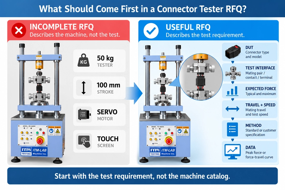
There is nothing unusual about this RFQ. The problem is that it describes the machine the buyer thinks they need, but almost nothing about the test the machine has to perform.
A 50 kg capacity does not tell the supplier whether the connector normally mates at 10 N or 200 N. It says nothing about mating travel, test speed, fixture geometry, alignment, seals, latches, data acquisition, or whether the application is a single force measurement or a repeated durability test.
Those details are what determine the actual test system.
If you are preparing an RFQ for a connector insertion and extraction force tester, start with the connector and the measurement. Machine capacity comes later.
Start With the Connector, Not the Tester
The first useful question is not:
How large a tester do you need?
It is:
What exactly are you testing?
“Connector” can mean anything from a miniature contact used in compact electronics to a sealed multi-position automotive connector with a housing, gasket, secondary lock, wires, and a relatively long mating path.
Two products can therefore require similar peak forces while needing completely different fixtures and motion arrangements.
Start the RFQ by identifying the DUT:
- Connector type and model
- Male and female mating parts
- Overall dimensions
- Mating direction
- Cable or wire arrangement
- Number of positions or contacts
- Latch, seal, lock, or secondary locking features
- Drawing, photographs, or CAD data if available
Then define the actual test interface.
It may be a complete mating connector pair, an individual contact pair, a terminal entering a housing, a plug entering a finished-device receptacle, or a contact tested against a specified gauge.
These configurations should not be treated as interchangeable simply because all of them involve insertion and withdrawal.
Define the Mechanical Event You Need to Measure
“Connector insertion force” is often used as a general description, but several different mechanical tests can sit behind that phrase.
You may need to measure complete connector mating force, for example, where the male and female connector assemblies are engaged as a system.
You may instead need unmating or extraction force, individual contact insertion or withdrawal force, terminal insertion into a housing, terminal retention or pull-out force, or the force associated with a latch or locking feature.
These are not simply different names for the same test.
The distinction matters because the load cell sees everything transmitted through the mechanical test path.
For a complete sealed connector, the measured force may contain contributions from contact interaction, housing guidance, seal compression, and other mechanical features permitted by the defined test configuration.
For an individual contact test, the measurement boundary may be much narrower.
So instead of writing:
Application: Connector force
write something closer to:
Test required: Complete connector mating and unmating force
or:
Test required: Individual female-contact insertion and withdrawal force against specified test gauge
If the test is controlled by IEC 60512, EIA-364, an automotive specification, a customer drawing, or an internal SOP, identify the applicable document and test method in the RFQ.
If your requirement specifically references IEC 60512-13-2 Test 13b, the measurement boundary deserves particular attention. Our separate IEC 60512-13-2 Test 13b Connector Insertion & Withdrawal Force Testing Guide covers that method in detail.
The standard number is useful. The exact test requirement is better.
Machine Capacity Is Not Your Working Force
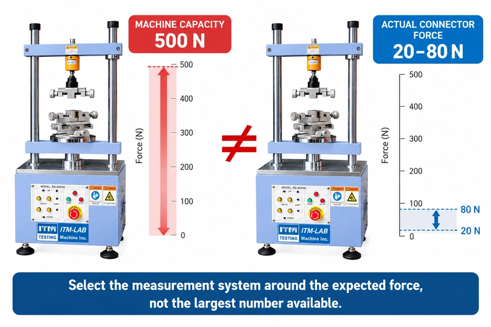
This is one of the most common connector force tester specification problems.
A buyer asks for a:
500 N tester
or:
50 kg connector tester
But the connector in the attached drawing may actually require only 15–25 N to mate.
Those are two different pieces of information.
The first describes an equipment limit.
The second describes the measurement the laboratory actually cares about.
Consider three applications:
| Application | Expected Force | What Else Changes |
|---|---|---|
| Small electronics connector | 8–15 N | Low-force measurement, compact fixture |
| Sealed multi-pin connector | 80–150 N | Housing fixture, alignment, longer travel |
| Terminal retention test | Up to 350 N | Pull-out fixture, different mechanical event |
All three buyers could potentially send an RFQ asking for a “50 kg connector tester.”
That does not make them the same test system.
For load-cell selection, tell the supplier what you know about the actual load:
Expected normal force: _____ N
Highest expected force: _____ N
If you already have historical measurements, include them.
If you do not know the expected force, do not invent a machine capacity simply to complete the RFQ. Send the connector information and explain that the range is unknown.
A preliminary test, existing product data, or representative sample may provide a better basis for configuration.
Think in Terms of the Usable Test Envelope
Travel is another specification that is easy to oversimplify.
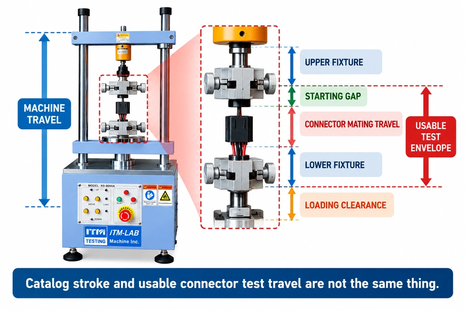
Suppose your connector moves 40 mm from first engagement to its fully mated position.
Does that mean you need a tester with 40 mm of travel?
Not necessarily.
The machine also has to accommodate the physical test setup. Depending on the fixture, you may need additional movement for the starting gap, approach, complete withdrawal, specimen loading, and clearance between fixture components.
It is more useful to think in terms of a usable test envelope:
Starting Position → Approach → First Contact → Mating Travel → Fully Mated Position → Withdrawal
The fixtures themselves also occupy physical space.
A catalog may therefore show adequate machine travel while the assembled connector and fixture leave insufficient usable motion for the intended procedure.
The Endpoint Matters Too
Travel is not only a question of whether the machine can move far enough.
The machine also needs to know where to stop.
Stopping too early can leave the connector partially mated.
Driving beyond the intended endpoint can force the connector against a housing stop or fixture feature and create a force peak that does not represent normal mating behavior.
For unusual connectors, show both positions in the drawing:
START
and
FULLY MATED
That can be more useful than simply writing:
Travel = 40 mm
Test Speed Comes From the Method
Another weak RFQ line is:
Speed: Adjustable
Adjustability is an equipment feature. It is not a test condition.
If the laboratory must test at 25 mm/min, 50 mm/min, or another specified speed, state that requirement directly.
For example:
Required test speed: 50 mm/min
Or, if the condition comes from a test procedure:
Test speed: According to the applicable customer test method
This becomes especially important when results will be compared between laboratories, suppliers, or production sites.
Changing the motion condition can change the measured response of a mechanical interface.
There is another distinction worth making:
Force-characterization speed is not necessarily the same as durability-cycle rate.
A controlled insertion force measurement may be performed at one motion condition, while repeated cycling for mechanical durability may use another.
If both functions are required, define both.
Do not collapse them into a single line called “test speed.”
The Fixture Is Part of the Measurement System
The fixture is often treated as an accessory in a purchasing specification.
Mechanically, it is part of the test.
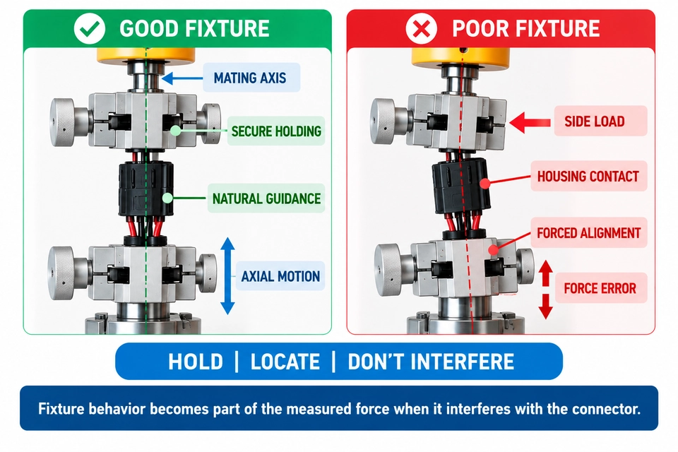
A connector fixture has three jobs:
Hold — prevent unwanted specimen movement.
Locate — establish a repeatable position and mating axis.
Do not interfere — avoid creating a mechanical condition that the connector would not normally experience.
The third job is easy to overlook.
A fixture does not only need to know what to hold. It needs to know what not to hold.
Imagine that both connector halves are clamped rigidly but their axes are offset slightly.
During mating, the housings may rub. Guide features may be forced sideways. The connector may no longer be able to establish its intended alignment.
The load cell still records a force.
The result may even be very repeatable.
But part of that force now belongs to the fixture-created misalignment.
For fixture design, provide the supplier with the connector drawing, mating direction, available holding surfaces, housing material, cable or wire exit direction, latch position, seal location, and any features that must remain free during mating.
If the connector uses its own guidance features to establish alignment, mention that as well.
Do not assume that making both sides “as rigid as possible” automatically improves the measurement.
Peak Force or Force-Travel Curve?
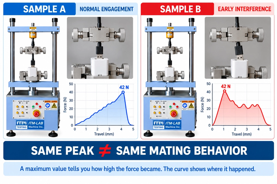
Suppose two connector samples both produce:
Peak insertion force: 42 N
Are they mechanically behaving the same way?
Not necessarily.
Sample A may rise smoothly through contact engagement and reach 42 N near full mating.
Sample B may reach 42 N much earlier because the housing starts rubbing against a guide or fixture.
If the test report contains only one maximum value, both samples look similar.
The force-travel curves tell two different stories.
The same peak value does not necessarily describe the same mating event.
For some QC applications, maximum insertion force, maximum extraction force, and pass/fail status may be all that is required.
For development, troubleshooting, or detailed mechanical evaluation, the laboratory may also need:
- Force vs. displacement curve
- Peak position
- Individual test traces
- Cycle comparison
- Raw data export
A curve can help associate a force change with a physical event in the mating path.
The important point is not that every customer needs a curve.
It is that the software and data-acquisition requirement should be defined before the tester is quoted, not discovered after installation.
Force Measurement and Durability Are Different Jobs
This distinction deserves to be made explicitly in a connector tester RFQ.
A force tester may be used to characterize a small number of controlled insertion and withdrawal events.
A durability system may need to repeat the mating operation thousands, tens of thousands, or more times.
Those requirements place different emphasis on the equipment.
For force measurement, you may care primarily about controlled motion, force measurement, displacement data, curve acquisition, and peak detection.
For durability cycling, cycle rate, cycle count, automatic reversal, fixture endurance, long-duration operation, and failure monitoring become more important.
Some projects need both.
For example:
Measure insertion and extraction force on the new connector, complete 10,000 mating cycles, then repeat the force measurement and compare the results.
That should be stated as a combined requirement.
If the primary objective is repeated insertion/extraction cycling rather than precision force characterization, treat the application as a durability requirement from the beginning rather than assuming it is simply the same force tester running longer.
A useful RFQ therefore states:
Force measurement required: Yes / No
Repeated cycling required: Yes / No
Number of cycles: _____
Force measured during cycling: Yes / No
Force measured before / after cycling: Yes / No
When Electrical Monitoring Matters
For some connector programs, the mechanical result is only half the question.
You may also need to know whether electrical performance remains acceptable during or after mechanical operation.
Depending on the project, that might involve:
Continuity
Interruption detection
Contact resistance
Customer-defined electrical monitoring
Do not assume that electrical monitoring is automatically included with a mechanical connector force tester.
If you need it, put it in the RFQ.
For example:
Electrical continuity must be monitored during repeated insertion/extraction cycling.
That tells the supplier that the test architecture must consider both mechanical motion and electrical connections.
If electrical measurement is not required, there is no reason to complicate the system specification with it.
Drawing, CAD File, or Physical Sample?
A common procurement question is how much product information the supplier actually needs before quotation.
There is no single answer.
A Dimensioned Drawing May Be Enough When
The connector geometry is simple, the holding surfaces are obvious, and the mating direction is well defined.
Drawing + Photographs Are Better When
The housing contains latches, ribs, wire exits, seals, or irregular external geometry that is difficult to understand from a 2D drawing alone.
A Physical Sample Is Strongly Preferred When
The clamping surfaces are irregular, the housing is flexible, the cable or harness affects mounting, or the connector's natural mating behavior is difficult to reproduce from drawings.
CAD data can also be useful when a custom fixture must follow complex molded geometry.
For confidential projects, a simplified interface drawing may be enough for a preliminary quotation. Detailed fixture engineering can follow once the necessary project information is available.
A practical rule works well:
The more application-specific the fixture, the more valuable the physical DUT becomes.
Throughput Changes the Practical Configuration
The same connector test can be performed five times per day or several hundred times per day.
The test method may not change.
The equipment workflow probably will.
For low-volume R&D work, manual specimen positioning and occasional fixture adjustment may be acceptable.
For regular QC or production-support testing, fixture loading time, repeatable positioning, automatic return, recipe storage, data naming, reporting, and fixture changeover can become much more important.
So add one simple line to the RFQ:
Expected volume: _____ specimens/day
Also mention whether the machine will test one connector model or many.
A laboratory running twelve connector families on one tester has a different fixture-management problem from a laboratory dedicated to one production connector.
Throughput is therefore not just a purchasing statistic. It can affect how the system should be configured.
Before You Send the RFQ
A connector force tester RFQ does not need to become a twenty-page engineering specification.
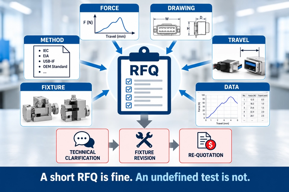
But six missing items commonly lead to another round of technical clarification before a meaningful configuration can be prepared.
No expected force. If you know the approximate working force, provide it. If not, state that it is unknown instead of guessing a machine capacity.
No DUT drawing. The machine may be straightforward to select while the fixture remains impossible to define.
No travel information. Provide the connector movement or start/end positions, not only a requested machine stroke.
No test method. Identify the applicable standard, customer specification, drawing requirement, or internal SOP.
No fixture information. Show how the connector can be held and which features must remain unobstructed.
No data requirement. State whether you need peak values, force-travel curves, raw data, pass/fail limits, or another reporting format.
Turning a Real RFQ Into an RS-6600A Configuration
Now return to the more useful RFQ from the beginning:
DUT: 24-position sealed automotive connector
Test: Complete mating and unmating force
Expected force: Below 150 N
Approximate mating travel: 45 mm
Required test speed: 50 mm/min
Required data: Peak force and force-travel curve
Daily volume: Approximately 40 connector pairs
Drawing: Available
At this point, equipment configuration becomes an engineering exercise rather than a guess.
The expected force provides the starting point for load-cell selection.
The connector drawing and sample geometry determine the fixture concept.
The 45 mm mating movement allows the complete usable test envelope to be checked once the connector and fixtures are considered.
The required speed defines the relevant motion condition.
The force-travel requirement defines what must be captured and reported.
The daily test volume helps determine whether loading, changeover, and software workflow require additional attention.
For an ITM-LAB RS-6600A Automatic Insertion and Extraction Force Tester, these application inputs can then be mapped to the appropriate test configuration.
The sequence is deliberate:
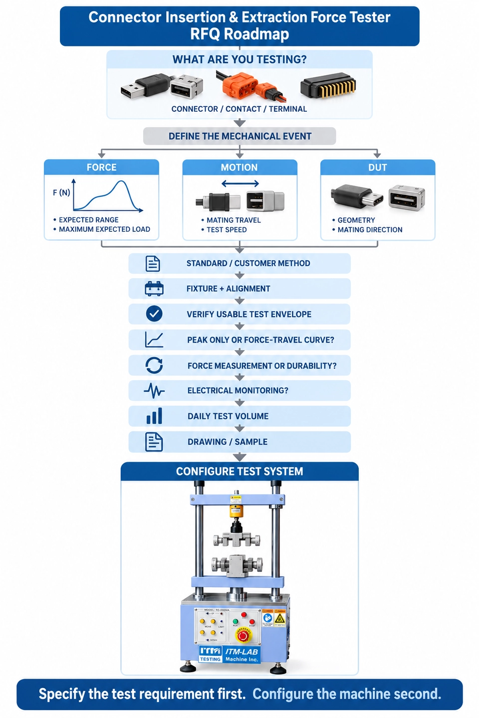
Connector → Test → Force → Motion → Fixture → Data → Machine
Not:
Machine → try to make the connector fit it
That distinction becomes increasingly important when the fixture is customized or when several connector models must share the same system.
A Better Connector Tester RFQ Starts With the Test
There is no need for the buyer to design the test machine.
That is the supplier's job.
But the supplier needs enough information to understand the measurement.
For connector force testing, five distinctions are particularly useful:
Machine capacity is not the same as working force.
Connector mating travel is not the same as catalog machine stroke.
A fixture is part of the measurement system, not just a way to hold the DUT.
Peak force is not the same as force-travel behavior.
Force characterization is not the same as durability cycling.
Define those points before comparing quotations.
A lower or higher machine capacity, different fixture, different load cell, or different software configuration can then be evaluated in the context of the actual test rather than as isolated specifications on a datasheet.
And if the expected force is still unknown, that is not a problem.
Send the connector drawing, test method, and available sample information rather than guessing a capacity.
Connector Force Tester RFQ Template
Instead of sending:
“Please quote a 50 kg connector insertion force tester.”
send the information below.
DUT / Connector: _____
Connector Model: _____
Drawing: Attached / Not Available
Test Required: _____
Test Interface: Connector Pair / Contact Pair / Terminal / Test Gauge
DUT Size: _____ × _____ × _____ mm
Expected Normal Force: _____ N / Unknown
Maximum Expected Force: _____ N / Unknown
Mating / Test Travel: _____ mm
Test Speed: _____ mm/min
Standard / Customer Method: _____
Latch / Seal / Lock Present: Yes / No
Peak Force Required: Yes / No
Force-Travel Curve Required: Yes / No
Repeated Cycling Required: Yes / No
Required Cycles: _____
Electrical Monitoring Required: Yes / No
Daily Test Volume: _____ specimens/day
Physical Sample Available: Yes / No
Other Requirements: _____
Attach the connector drawing, mating-interface photographs, and applicable test specification whenever available.
If you do not know the force range yet, send the connector information rather than guessing the machine capacity.
That gives the equipment supplier a much better starting point:
DUT → Force → Travel → Fixture → Load Cell → Motion → Data → Test System
