
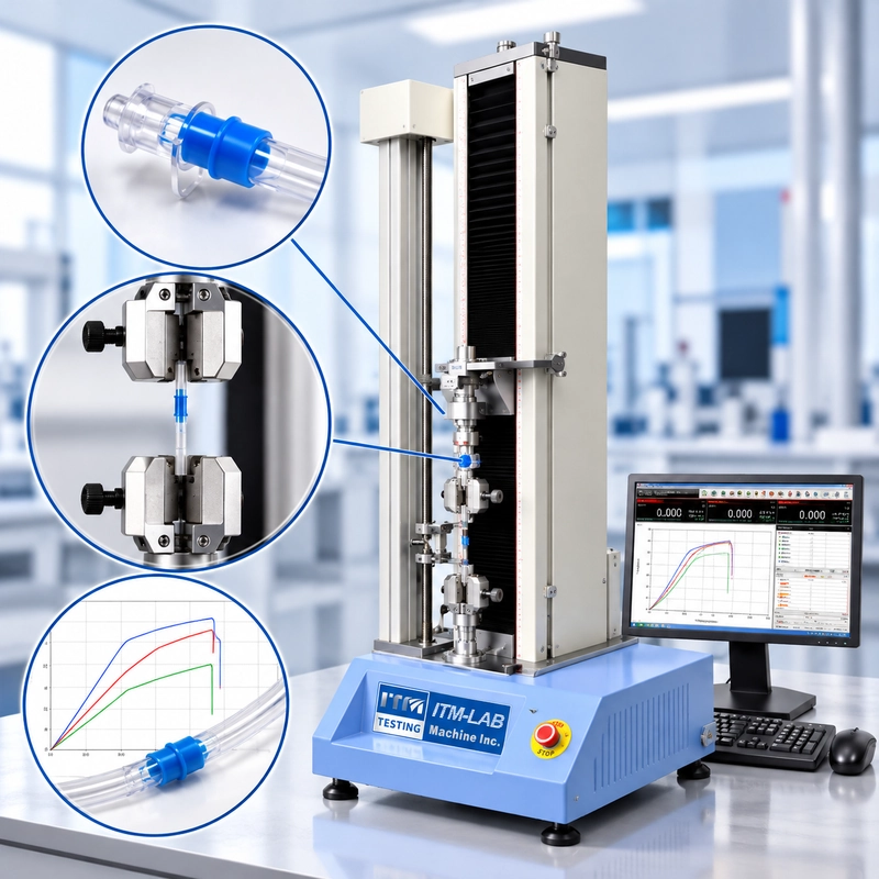
A catheter hub withstands a specified tensile load, but the tubing slips inside the grip before the connection separates.
Does that mean the joint passed?
Not necessarily.
Catheter tensile testing is not simply about recording the highest force. The result must represent the intended connection, under the correct loading conditions, without interference from gripping damage, slippage or misalignment.
For medical device manufacturers, three factors are particularly important: the applicable tensile requirement, the actual failure location and the measurement system used to perform the test.
This guide explains how these factors influence catheter joint strength testing and the selection of suitable test equipment.
What Does Catheter Tensile Testing Measure?
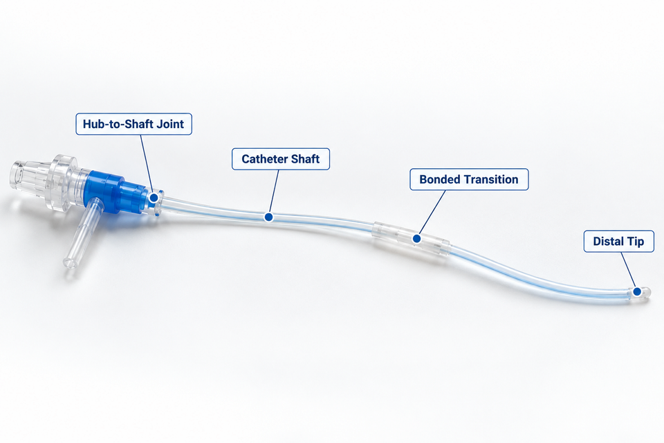
Catheter tensile testing may evaluate the strength of the tubing itself or the integrity of connections within the assembly.
These are different test objectives.
A catheter shaft may withstand a relatively high tensile force while its bonded hub separates at a lower load. Conversely, the tubing may rupture before the hub connection fails.
The test location must therefore be defined before selecting the gripping fixtures.
|
Test location |
Main objective |
Possible failure |
|---|---|---|
|
Hub-to-shaft |
Hub retention strength |
Bond separation or pullout |
|
Catheter shaft |
Tubing tensile behavior |
Rupture or elongation |
|
Distal tip |
Tip connection integrity |
Tip separation |
|
Bonded transition |
Joint strength |
Adhesive or cohesive failure |
The connections requiring evaluation depend on the catheter design, intended use and applicable product requirements.
ISO 10555-1 Tensile Force Requirements
ISO 10555-1:2023 specifies general requirements for sterile, single-use intravascular catheters, including tensile testing provisions for applicable catheter portions and connections.
It should not be treated as a universal test standard for every medical catheter.
For applicable tubular portions, the standard includes the following minimum peak tensile force requirements.
|
Smallest outside diameter |
Minimum peak tensile force |
|---|---|
|
0.55 to less than 0.75 mm |
3 N |
|
0.75 to less than 1.15 mm |
5 N |
|
1.15 to less than 1.85 mm |
10 N |
|
1.85 mm and above |
15 N |
These values are subject to the relevant provisions and exceptions of the standard. Product-specific requirements may differ, and the applicable edition should be checked when defining the test.
An important distinction is that the minimum acceptance force is not necessarily the maximum force encountered during testing.
For example, a catheter joint with a 15 N acceptance requirement may remain intact until a higher load. If the test requires loading to separation, the machine must accommodate the anticipated failure force as well as measure the acceptance threshold reliably.
Test Setup: Gripping, Alignment and Loading
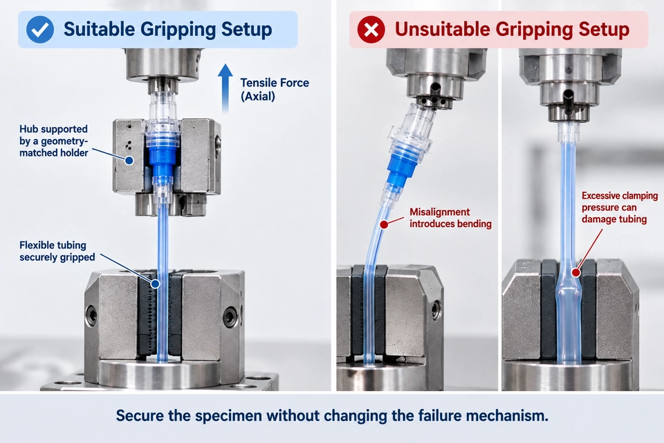
Flexible catheter tubing presents different gripping challenges from conventional metal or rigid plastic specimens.
Excessive clamping pressure can flatten or damage the tube. Insufficient pressure may allow the specimen to slip before the intended joint fails.
For hub pull testing, a dedicated holder may be needed to support the rigid connector while a suitable grip secures the flexible shaft.
A reliable setup should address three questions:
-
Gripping: Can the specimen be held without slipping or suffering local damage?
-
Alignment: Is tensile force applied along the intended loading axis?
-
Test conditions: Are the required speed, conditioning and test endpoint correctly defined?
The applicable standard or validated procedure determines the detailed loading conditions.
Where specimen conditioning is required, the preparation conditions should be distinguished from the environment during the tensile test.
The test report should include the peak force, test location, relevant conditions and observed failure mode.
Crosshead displacement can help identify unusual movement, but it should not automatically be interpreted as the actual extension of the catheter joint.
Why Failure Location Matters
Two catheter specimens can produce the same peak force while providing very different information about joint strength.
Consider two illustrative hub pull tests, both recording 18 N.
In the first test, the bonded joint separates at 18 N without grip slippage.
In the second, the catheter shaft slips through the grip at 18 N while the joint remains intact.
The recorded force is identical, but the second result does not establish the joint's ultimate separation strength.
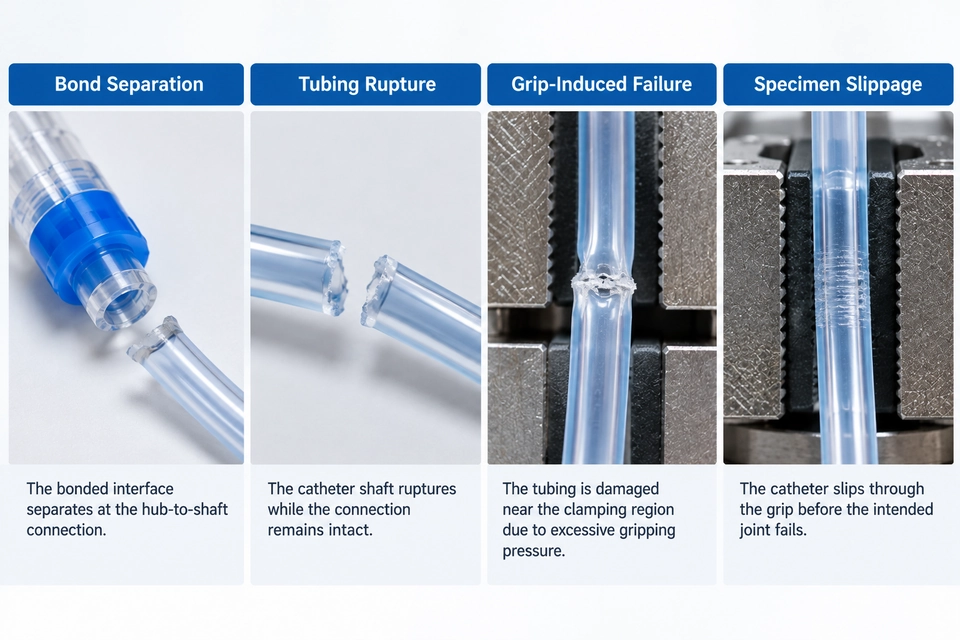
Common failure modes include:
|
Failure mode |
Interpretation |
|---|---|
|
Bond separation |
May represent the intended joint failure |
|
Tubing rupture |
Joint remained intact up to the recorded force; ultimate joint strength may remain unknown |
|
Grip-induced rupture |
Possible fixture-related failure requiring investigation |
|
Specimen slippage |
Does not establish ultimate joint strength |
Whether a result is acceptable depends on the test objective and applicable validity criteria.
A tubing rupture may be sufficient to demonstrate resistance to a specified minimum load in some procedures, even though the ultimate joint separation force was not measured.
Peak force alone does not explain what failed. The failure location is part of the result.
Choosing a Catheter Tensile Testing Machine
Catheter tensile testing often involves relatively low forces. Selecting the machine only by maximum capacity can therefore be misleading.
Consider an illustrative catheter joint with an expected failure force of 12 N.
|
Parameter |
50 N load cell |
5 kN load cell |
|---|---|---|
|
Rated capacity |
50 N |
5,000 N |
|
Expected test force |
12 N |
12 N |
|
Percentage of capacity |
24% |
0.24% |
Both sensors have sufficient nominal capacity to measure 12 N.
However, their suitability depends on the verified accuracy, calibration coverage and measurement stability at that force.
The comparison does not establish that a 50 N sensor is automatically more accurate. It illustrates why the actual working force range must be considered.
ITM-LAB RS-8010A Single-Column Tensile Testing Machine
The ITM-LAB RS-8010A provides selectable force capacities and computer-controlled tensile loading for lower-force mechanical testing applications.
|
Specification |
RS-8010A |
|---|---|
|
Force capacity options |
50 N–5 kN |
|
Accuracy class |
Level 0.5 |
|
Load resolution |
1/500,000 |
|
Test speed |
0.01–500 mm/min; up to 1000 mm/min optional |
|
Standard stroke |
650 mm, excluding grips |
|
Optional stroke |
1000 mm |
|
Stroke resolution |
0.001 mm |
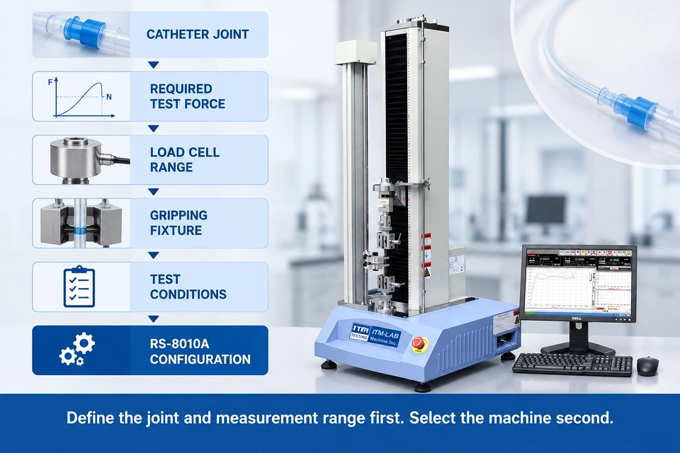
For catheter tensile and joint strength testing, the RS-8010A may be evaluated with a suitable lower-capacity load cell and application-specific gripping fixtures.
The final configuration depends on the expected test force, catheter geometry, required measurement accuracy and applicable procedure.
Published machine specifications alone do not establish compliance with ISO 10555-1.
Conclusion
Reliable catheter tensile testing requires more than sufficient machine capacity.
The specimen must be gripped correctly, the intended connection must receive the required tensile load, and the recorded result must be interpreted according to the actual failure mode.
For low-force applications, load cell measurement range and fixture design are often as important as the machine itself.
Define the catheter joint, expected force and test conditions first. Select the testing system second.
ITM-LAB offers the RS-8010A single-column universal testing machine with selectable force capacities and fixture configuration options.
For catheter tensile or joint strength testing, provide your catheter dimensions, joint drawings, applicable standard and expected force range to discuss a suitable test configuration.
