
1. Core Definitions & Working Principles
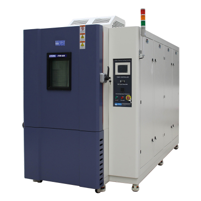
Thermal Shock Chamber
-
Key Characteristics: Transfer time <10 seconds (air-to-air) or <1 second (liquid immersion); steep thermal gradients across the specimen; instantaneous stress from surface-to-core temperature differentials; fewer test cycles (10–1000).
-
Transfer Methods:
-
Air-to-air: Pneumatic/mechanical basket transfer between hot and cold zones (moderate shock, ideal for electronics and assemblies).
-
Liquid immersion: Alternate immersion in hot/cold fluid baths (extreme shock, 10–100× better heat transfer than air, suitable for materials testing).
![]()
-
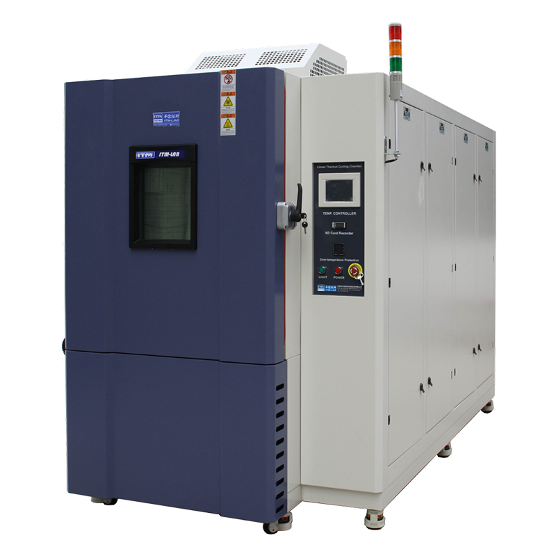
Temperature Cycling Chamber
-
Key Characteristics: Controlled ramp rates (0.5–20°C/min, typically 1–15°C/min); extended dwell times at temperature extremes (10 minutes to 4 hours) to ensure thermal equilibrium; uniform temperature distribution across the specimen; cumulative fatigue from repeated expansion-contraction cycles; more test cycles (100–5000).
-
Typical Profile Example: Start at 25°C → ramp to 85°C (5°C/min) → dwell 30 minutes → ramp to -40°C (5°C/min) → dwell 30 minutes → return to 25°C (1 cycle = 97 minutes).
![]()
2. Stress Mechanisms & Failure Modes
Thermal Shock: Instantaneous Stress & Acute Failures
Key Stress Mechanisms
-
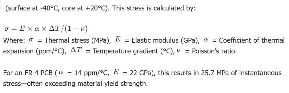
Thermal Gradient Stress (Dominant): During rapid temperature change, the specimen’s surface adjusts to the new temperature while the core lags, creating a steep temperature differential. For example, a 10mm thick component transferred from 25°C to -55°C can develop a 60°C gradient.
-
CTE Mismatch Stress: Different materials expand/contract at different rates (e.g., silicon die: 2.6 ppm/°C vs. FR-4 PCB: 14 ppm/°C). A 140°C temperature change creates 0.16% differential expansion, leading to shear stress at interfaces and delamination.
Common Failure Modes
-
Brittle Fracture: Immediate failure in ceramics, glass, or brittle plastics—cracks initiate at surface flaws and propagate rapidly (occurs in the first few cycles if shock is too severe).
-
Delamination: PCB layer separation, coating debonding, or adhesive failure—caused by CTE mismatch and shear stress accumulation (occurs in 10–500 cycles).
-
Solder Joint Cracking: Accelerated fatigue in BGA, QFN, or CSP packages—rapid crack growth from thermal gradients and CTE mismatch (occurs in 50–1000 cycles, much faster than temperature cycling).
-
Package Cracking: Moisture-induced failure in plastic IC packages—moisture vaporizes during hot shock, creating internal pressure that cracks the package (occurs in the first hot shock cycle if moisture is present).
Temperature Cycling: Cumulative Fatigue & Progressive Failures
Key Stress Mechanism: Cumulative Thermal Fatigue
Common Failure Modes
-
Solder Joint Fatigue: Dominant failure mode—cracks initiate at joint edges and propagate across the joint (occurs in 100–10,000 cycles, depending on ΔT and package type).
-
Wire Bond Fatigue: Gold or aluminum wire bond lift-off from dies or lead frames—caused by repeated differential expansion (occurs in 500–5000 cycles).
-
PCB Copper Trace Fatigue: Crack propagation in plated through-holes (PTH)—resulting from Z-axis expansion of the board vs. copper barrels (occurs in 1000–10,000 cycles).
-
Interconnect Fatigue: Connector contact degradation or crimp terminal loosening—accelerated by micro-movement and fretting corrosion (occurs in 1000–5000 cycles).
3. Test Standards & Technical Specifications
Thermal Shock Chamber: Standards & Specifications
Core Standards
-
IEC 60068-2-14: Test Na (two-liquid-bath thermal shock) & Test Nb (air thermal shock) — Transfer time <10 seconds (liquid) or <1 minute (air); temperature range -55°C to +150°C; 5–500 cycles.
-
JEDEC JESD22-A106: Thermal shock for electronic components — Transfer time <10 seconds (air) or <1 second (liquid); temperature ranges: 0°C–100°C (mild), -55°C–125°C (standard), -65°C–150°C (severe); 100–1000 cycles.
-
MIL-STD-810H Method 503: Temperature shock for military/aerospace equipment — Mission-specific parameters; transfer time <5 minutes; 3–5 cycles typical.
-
SAE J1211: Automotive environmental practices — -40°C to +85°C, <10 second transfer, 200 cycles.
Technical Specifications (Industry Standard)
-
Temperature Range: -70°C to +200°C (zone-dependent)
-
Transfer Time: <10 seconds (air-to-air); <1 second (liquid immersion)
-
Temperature Uniformity: ±3°C (hot/cold zones)
-
Dwell Time: 10–30 minutes per zone (until thermal equilibrium)
-
Cycle Count: 10–1000 cycles
-
Chamber Volume: 50–500L per zone (benchtop to reach-in)
Temperature Cycling Chamber: Standards & Specifications
Core Standards
-
IEC 60068-2-14: Test Nc (rapid temperature change) — Ramp rate ≥5°C/min; -55°C to +125°C; 5 cycles typical (bridges shock and cycling).
-
JEDEC JESD22-A104: Temperature cycling for electronic components — Ramp rate 10–15°C/min; temperature ranges: -55°C–85°C (consumer), -55°C–125°C (automotive), -65°C–150°C (military); 200–2000 cycles.
-
MIL-STD-810H Method 503: Temperature variation procedures — Gradual ramp rates; tailored to operational environments.
-
AEC-Q100: Automotive semiconductor qualification — Test G (temperature cycling per JESD22-A104 Condition B); -40°C–125°C (Grade 1) or +150°C (Grade 0); 1000+ cycles.
Technical Specifications (Industry Standard)
-
Temperature Range: -70°C to +180°C (single zone)
-
Ramp Rate: 0.5–20°C/min (programmable, linear/exponential/stepped)
-
Temperature Uniformity: ±2°C (per IEC 60068-3-5)
-
Dwell Time: 10 minutes to 4 hours per extreme
-
Cycle Count: 100–5000 cycles
-
Chamber Volume: 100–1000L (larger than shock chambers)
4. Step-by-Step Practical Test Procedures
Thermal Shock Test Procedure (Air-to-Air, JEDEC JESD22-A106 Standard)
-
Sample Preparation:
-
Sample quantity: 3–5 pieces (including 1 control sample).
-
Pre-conditioning: Stabilize at 25°C/50%RH for 24 hours to eliminate initial moisture and thermal stress.
-
Mounting: Free-hang specimens in the transfer basket (minimal fixturing to avoid constraining thermal expansion).
-
-
Chamber Preparation:
-
Preheat hot zone to 125°C and precool cold zone to -55°C (standard condition).
-
Verify temperature stability (±3°C) and uniformity in both zones before starting.
-
-
Test Execution:
-
Load specimens into the hot zone → dwell for 15 minutes (thermal equilibrium).
-
Transfer to the cold zone in ≤10 seconds → dwell for 15 minutes.
-
Repeat for 100 cycles (no intermediate inspection—focus on catastrophic failure).
-
-
Post-Test Inspection:
-
Visual inspection: Use 10–20x microscope to check for cracks, delamination, package damage, or solder joint failure.
-
Functional testing: Retest electrical/mechanical performance and compare to pre-test baseline.
-
Failure analysis: Identify root causes (e.g., CTE mismatch, thermal gradient stress, moisture absorption).
-
Temperature Cycling Test Procedure (JEDEC JESD22-A104 Standard)
-
Sample Preparation:
-
Sample quantity: 3–5 pieces (including 1 control sample).
-
Pre-conditioning: Stabilize at 25°C/50%RH for 24 hours.
-
Mounting: Use racks to elevate specimens (avoid direct contact with chamber shelves to prevent heat sink effects); attach PT100 thermocouples (±0.1°C) to critical surfaces.
-
-
Program Setup:
-
Profile: 25°C → ramp to 85°C (10°C/min) → dwell 30 minutes → ramp to -40°C (10°C/min) → dwell 30 minutes → return to 25°C (1 cycle).
-
Cycle count: 500 cycles (consumer electronics) or 1000 cycles (automotive).
-
-
Test Execution:
-
Start the program and monitor real-time data (chamber temperature, specimen temperature, cycle count).
-
Pause every 100 cycles to inspect for early signs of failure (e.g., signal instability, parameter drift).
-
Stop test early if failures occur (e.g., functional loss, crack propagation ≥0.1mm).
-
-
Post-Test Inspection:
-
Visual inspection: Check for material aging, discoloration, solder joint cracks, or PCB delamination.
-
Functional testing: Full parameter retest to compare with initial performance.
-
Failure analysis: Use Coffin-Manson equation to predict fatigue life and identify design improvements.
-
5. Industry Applications & Compliance
When to Use Thermal Shock Chambers
-
Aerospace & Defense: Avionics, satellite components, missile parts (simulate rapid altitude changes; comply with MIL-STD-810H Method 503).
-
Semiconductors (Package Integrity): ICs, ceramic capacitors (MLCC), discrete components (test for package cracking, die attach failure; comply with JEDEC JESD22-A106).
-
Automotive (Underhood Rapid Stress): Engine sensors, ECUs (simulate sudden engine startup; comply with SAE J1211).
-
Materials & Coatings: Conformal coatings, adhesives, glass-to-metal seals (test for delamination, brittle fracture; comply with ASTM D2247, ASTM D3433).
When to Use Temperature Cycling Chambers
-
Consumer Electronics: Smartphones, tablets, batteries, chargers (simulate daily use/global shipping; comply with JEDEC JESD22-A104 Condition A).
-
Automotive (Long-Term Reliability): In-vehicle infotainment, dashboard components (simulate day-night cycling; comply with AEC-Q100, SAE J1211).
-
Medical Devices: Diagnostic equipment, patient monitors (validate long-term reliability in clinical environments; comply with ISO 14971, IEC 60601).
-
Industrial Controls: PLCs, power supplies, industrial sensors (simulate factory temperature swings; comply with IEC 61010).
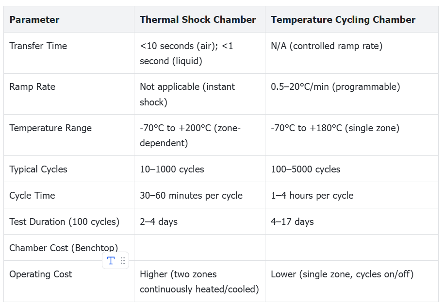
6. Equipment Comparison: Key Parameters
7. Common Mistakes & Best Practices
Common Mistakes to Avoid
-
Mistake 1: Using Thermal Shock for Gradual Cycling Applications — Example: Testing automotive electronics for under-hood cycling (engine heats up over 10–15 minutes). Consequence: Over-testing (lab failures that won’t occur in real use). Correct approach: Temperature cycling with 5–10°C/min ramp rate.
-
Mistake 2: Insufficient Dwell Time — For large-mass specimens, short dwell times mean the core never reaches the target temperature. Solution: Monitor specimen core temperature and extend dwell until thermal equilibrium (20–30 minutes for large parts).
-
Mistake 3: Incorrect Ramp Rate — Specifying a 15°C/min ramp rate for a chamber that only achieves 8°C/min (with test load) results in milder testing than intended. Solution: Verify chamber performance with actual test loads.
-
Mistake 4: Poor Specimen Mounting — Rigidly clamping specimens in thermal shock chambers induces extra stress; placing specimens on chamber shelves in cycling chambers causes heat sink effects. Solution: Free-hang shock specimens; elevate cycling specimens on racks.
Best Practices
-
Measure actual specimen temperature with thermocouples to ensure alignment with chamber specifications.
-
Document test rationale (operational environment analysis, parameter selection) for compliance audits.
-
Monitor product functionality during testing (e.g., power on electronics) to capture real-time failures.
-
Conduct post-test cross-sectioning and microscopic analysis to identify internal damage.
-
Use sequential testing (shock → cycling) for high-reliability products: shock screens for defects, cycling accumulates fatigue damage.
8. Conclusion
FAQs
-
Q: Can I use a thermal shock chamber for temperature cycling? A: No. Thermal shock chambers lack controlled ramp rates and uniform temperature distribution, leading to unrealistic stress and invalid fatigue data.
-
Q: How many cycles are needed for consumer electronics temperature cycling? A: Typically 500–1000 cycles (-40°C to +85°C, 10°C/min) to validate 3–5 years of daily use.
-
Q: What’s the difference between air-to-air and liquid immersion thermal shock? A: Liquid immersion offers faster heat transfer (10–100× better than air) and more extreme shock, but requires fluid-compatible specimens.
-
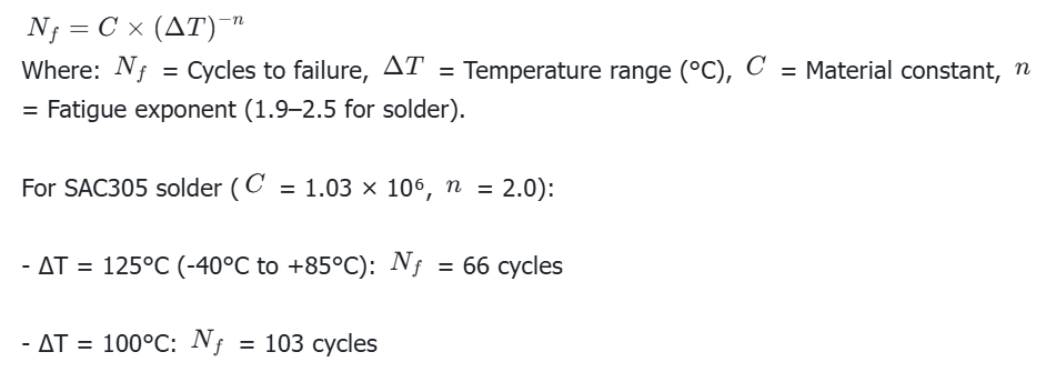
Q: How do I calculate cycles to failure for solder joints? A: Use the Coffin-Manson equation:
![]()

